M37161M8/MA/MF-XXXSP/FP,M37161EFSP/FP
2
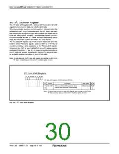
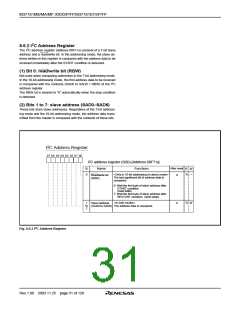
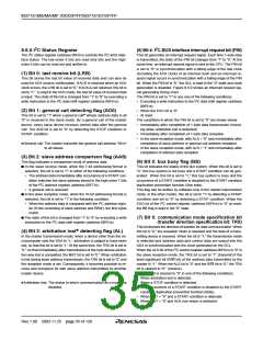
8.6.2 I C Address Register
2
The I C address register (address 00F716) consists of a 7-bit slave
address and a read/write bit. In the addressing mode, the slave ad-
dress written in this register is compared with the address data to be
received immediately after the START condition is detected.
(1) Bit 0: read/write bit (RBW)
Not used when comparing addresses in the 7-bit addressing mode.
In the 10-bit addressing mode, the first address data to be received
2
is compared with the contents (SAD6 to SAD0 + RBW) of the I C
address register.
The RBW bit is cleared to “0” automatically when the stop condition
is detected.
(2) Bits 1 to 7: slave address (SAD0–SAD6)
These bits store slave addresses. Regardless of the 7-bit address-
ing mode and the 10-bit addressing mode, the address data trans-
mitted from the master is compared with the contents of these bits.
2
I C Address Register
b7 b6 b5 b4 b3 b2 b1 b0
I2C address register (S0D) [Address 00F716]
After reset
0
B
0
Name
Functions
R W
R —
<Only in 10-bit addressing (in slave) mode>
The last significant bit of address data is
compared.
Read/write bit
(RBW)
0: Wait the first byte of slave address after
START condition
(read state)
1: Wait the first byte of slave address after
(write state)
RESTART condition
<In both modes>
(SAD0 to SAD6) The address data is compared.
R
W
Slave address
0
1
to
7
2
Fig. 8.6.3 I C Address Register
Rev.1.00 2003.11.25 page 31 of 128

 RENESAS [ RENESAS TECHNOLOGY CORP ]