M37161M8/MA/MF-XXXSP/FP,M37161EFSP/FP
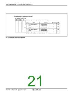
Interrupt Input Polarity Register
b7 b6 b5 b4 b3 b2 b1 b0
Interrupt input polarity register (RE) [Address 00DC16
]
B
0
Name
Functions
After reset
0
R
R
W
W
INT1 polarity switch bit
(INT1)
0 : Positive polarity
1 : Negative polarity
0
0
0
R
R
R
W
W
—
1
2
INT2 polarity switch bit
(INT2)
0 : Positive polarity
1 : Negative polarity
INT3 polarity switch bit
(INT3)
0 : Positive polarity
1 : Negative polarity
3
to
7
Nothing is assigned. These bits are write disable bits.
When these bits are read out, the values are “0.”
Fig. 8.3.6 Interrupt Input Polarity Register
Rev.1.00 2003.11.25 page 21 of 128

 RENESAS [ RENESAS TECHNOLOGY CORP ]