M37161M8/MA/MF-XXXSP/FP,M37161EFSP/FP
8.3 INTERRUPTS
8.3.1 Interrupt Sources
Interrupts can be caused by 16 different sources comprising 4 exter-
nal, 10 internal, 1 software, and reset. Interrupts are vectored inter-
rupts with priorities as shown in Table 8.3.1. Reset is also included in
the table because its operation is similar to an interrupt.
When an interrupt is accepted,
(1) VSYNC, OSD interrupts
The VSYNC interrupt is an interrupt request synchronized with
the vertical sync signal.
The OSD interrupt occurs after character block display to the
CRT is completed.
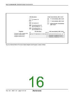
ꢀ The contents of the program counter and processor status regis-
ter are automatically stored into the stack.
ꢀ The interrupt disable flag I is set to “1” and the corresponding
interrupt request bit is set to “0.”
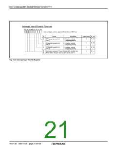
(2) INT1 to INT3 external interrupts
The INT1 to INT3 interrupts are external interrupt inputs, the sys-
tem detects that the level of a pin changes from LOW to HIGH or
from HIGH to LOW, and generates an interrupt request. The in-
put active edge can be selected by bits 3 to 5 of the interrupt
input polarity register (address 00DC16) : when this bit is “0,” a
change from LOW to HIGH is detected; when it is “1,” a change
from HIGH to LOW is detected. Note that both bits are cleared to
“0” at reset.
ꢀ The jump destination address stored in the vector address enters
the program counter.
Other interrupts are disabled when the interrupt disable flag is set to
“1.”
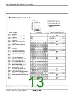
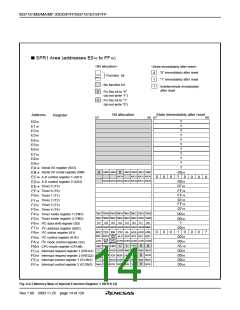
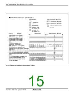
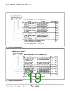
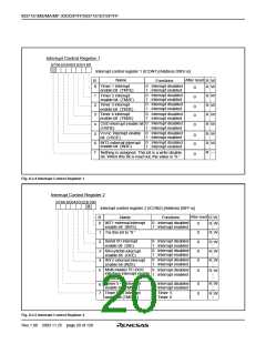
All interrupts except the BRK instruction interrupt have an interrupt
request bit and an interrupt enable bit. The interrupt request bits are
in interrupt request registers 1 and 2 and the interrupt enable bits are
in interrupt control registers 1 and 2. Figures 8.3.2 to 8.3.6 show the
interrupt-related registers.
(3) Timers 1 to 4 interrupts
Interrupts other than the BRK instruction interrupt and reset are ac-
cepted when the interrupt enable bit is “1,” interrupt request bit is “1,”
and the interrupt disable flag is “0.” The interrupt request bit can be
set to “0” by a program, but not set to “1.” The interrupt enable bit can
be set to “0” and “1” by a program.
An interrupt is generated by an overflow of timers 1 to 4.
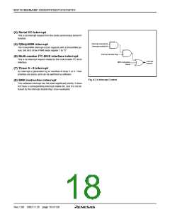
Reset is treated as a non-maskable interrupt with the highest priority.
Figure 8.3.1 shows interrupt control.
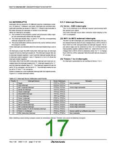
Table 8.3.1 Interrupt Vector Addresses and Priority
Priority
Interrupt Source
Vector Addresses
Remarks
1
2
Reset
FFFF16, FFFE16
FFFD16, FFFC16
FFFB16, FFFA16
FFF716, FFF616
FFF516, FFF416
FFF316, FFF216
FFF116, FFF016
FFEF16, FFEE16
FFED16, FFEC16
FFEB16, FFEA16
FFE916, FFE816
FFE716, FFE616
FFE516, FFE416
FFE316, FFE216
FFDF16, FFDE16
Non-maskable
OSD interrupt
3
INT1 external interrupt
Serial I/O interrupt
Timer 4 interrupt
Active edge selectable
4
5
6
f(XIN)/4096 interrupt
VSYNC interrupt
7
8
Timer 3 interrupt
9
Timer 2 interrupt
10
11
12
13
14
15
Timer 1 interrupt
INT3 external interrupt
INT2 external interrupt
Active edge selectable
Active edge selectable
2
Multi-master I C-BUS interface interrupt
Timer 5 • 6 interrupt
Source switch by software (see note)
Non-maskable
BRK instruction interrupt
Note: Switching a source during a program causes an unnecessary interrupt. Therefore, set a source at initializing of program.
Rev.1.00 2003.11.25 page 17 of 128

 RENESAS [ RENESAS TECHNOLOGY CORP ]