455A Group
EXTERNAL INTERRUPTS
The 455A Group has the external 0 interrupt. An external
interrupt request occurs when a valid waveform is input to an
interrupt input pin (edge detection).
The external interrupt can be controlled with the interrupt control
register I1.
Table 14 External interrupt activated conditions
Input pin
Activated condition
Valid waveform
selection bit
Name
External 0 interrupt
D5/INT
When the next waveform is input to D5/INT pin
I11
I12
• Falling waveform (“H” → “L”)
• Rising waveform (“L” → “H”)
• Both rising and falling waveforms
I12
Falling
One-sided edge
detection circuit
I11
0
(Note 1)
D5/INT
0
External 0
interrupt
EXF0
or
1
1
(Note 1)
Both edges
Rising
detection circuit
Timer 1 count start
synchronization
circuit input
SNZI0 instruction
Skip
I13
(Note 2)
K21
Level detection circuit
Edge detection circuit
(Note 3)
0
Key-on wakeup input
K20
1
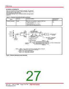
Note 1:
This symbol represents a parasitic diode on the port.
2: When I12= 0(X=0 or 1) is 0, “L” level is detected.
When I12 is 1, “H” level is detected.
3: When I12 is 0, falling edge is detected.
When I12 is 1, rising edge is detected.
Fig 28. External interrupt circuit structure
Rev.1.01 Feb 15, 2008 Page 27 of 146
REJ03B0224-0101

 RENESAS [ RENESAS TECHNOLOGY CORP ]