455A Group
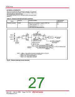
INTERRUPT FUNCTION
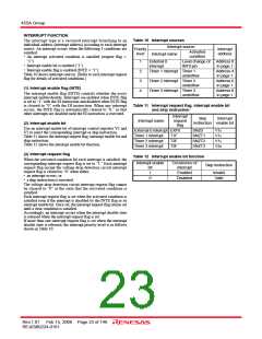
Table 10 Interrupt sources
The interrupt type is a vectored interrupt branching to an
individual address (interrupt address) according to each interrupt
source. An interrupt occurs when the following 3 conditions are
satisfied.
Interrupt source
Priority
level
Interrupt
address
Activated
condition
Interrupt name
• An interrupt activated condition is satisfied (request flag =
“1”)
1
2
3
4
External 0
interrupt
Level change of Address 0
• Interrupt enable bit is enabled (“1”)
INT0 pin
in page 1
• Interrupt enable flag is enabled (INTE = “1”)
Table 10 shows interrupt sources. (Refer to each interrupt request
flag for details of activated conditions.)
Timer 1 interrupt Timer 1
underflow
Address 4
in page 1
Timer 2 interrupt Timer 2
underflow
Address 6
in page 1
(1) Interrupt enable flag (INTE)
Timer 3 interrupt Timer 3
underflow
Address 8
in page 1
The interrupt enable flag (INTE) controls whether the every
interrupt enable/disable. Interrupts are enabled when INTE flag
is set to “1” with the EI instruction and disabled when INTE flag
is cleared to “0” with the DI instruction. When any interrupt
occurs, the INTE flag is automatically cleared to “0,” so that
other interrupts are disabled until the EI instruction is executed.
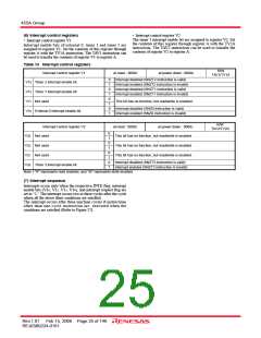
Table 11 Interrupt request flag, interrupt enable bit
and skip instruction
Interrupt
request
flag
Skip
Interrupt
Interrupt name
instruction enable bit
(2) Interrupt enable bit
Use an interrupt enable bit of interrupt control registers V1 and
V2 to select the corresponding interrupt or skip instruction.
Table 11 shows the interrupt request flag, interrupt enable bit and
skip instruction.
External 0 interrupt EXF0
SNZ0
V10
V12
V13
V20
Timer 1 interrupt
Timer 2 interrupt
Timer 3 interrupt
T1F
T2F
T3F
SNZT1
SNZT2
SNZT3
Table 12 shows the interrupt enable bit function.
(3) Interrupt request flag
Table 12 Interrupt enable bit function
When the activated condition for each interrupt is satisfied, the
corresponding interrupt request flag is set to “1.” Each interrupt
request flag except the voltage drop detection circuit interrupt
request flag is cleared to “0” when either;
• an interrupt occurs, or
• a skip instruction is executed.
Interrupt enable
bit
Occurrence of
interrupt
Skip instruction
1
0
Enabled
Disabled
Invalid
Valid
The voltage drop detection circuit interrupt request flag cannot
be cleared to “0” at the state that the activated condition is
satisfied.
Each interrupt request flag is set when the activated condition is
satisfied even if the interrupt is disabled by the INTE flag or its
interrupt enable bit. Once set, the interrupt request flag retains set
until a clear condition is satisfied.
Accordingly, an interrupt occurs when the interrupt disable state
is released while the interrupt request flag is set.
If more than one interrupt request flag is set when the interrupt
disable state is released, the interrupt priority level is as follows
shown in Table 10.
Rev.1.01 Feb 15, 2008 Page 23 of 146
REJ03B0224-0101

 RENESAS [ RENESAS TECHNOLOGY CORP ]