455A Group
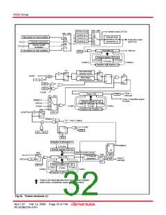
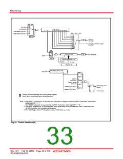
The 455A Group timer consists of the following circuits.
• Prescaler : 8-bit programmable timer
• Timer 1 : 8-bit programmable timer
• Timer 2 : 8-bit programmable timer
• Timer 3 : 16-bit fixed frequency timer
Prescaler, timer 1, timer 2, timer 3 and timer LC can be
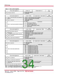
controlled with the timer control registers PA and W1 to W5. The
watchdog timer is a free counter which is not controlled with the
control register.
Each function is described below.
• Timer LC : 4-bit programmable timer
• Watchdog timer: 16-bit fixed frequency timer
(Timers 1, 2 and 3 have the interrupt function, respectively)
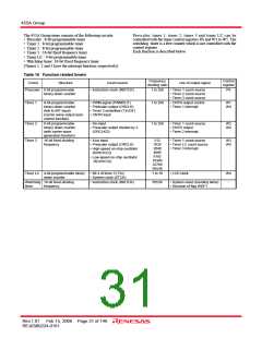
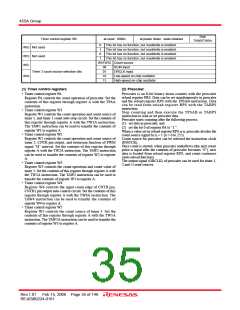
Table 16 Function related timers
Frequency
dividing ratio
Control
register
Circuit
Structure
Count source
Use of output signal
Prescaler 8-bit programmable
binary down counter
• Instruction clock (INSTCK)
1 to 256
• Timer 1 count source
• Timer 2 count source
• Timer 3 count source
PA
Timer 1
8-bit programmable
binary down counter
(link to INT input)
(carrier wave output auto-
control function)
• PWM signal (PWMOUT)
• Prescaler output (ORCLK)
• Timer 3 underflow (T3UDF)
• CNTR input
1 to 256
• CNTR output control
• Timer 1 interrupt
W1
W4
Timer 2
Timer 3
8-bit programmable
binary down counter
(with carrier wave
generation function)
• XIN input
• Prescaler output divided by 2
(ORCLK/2)
1 to 256
• Timer 1 count source
• CNTR output
• Timer 2 interrupt
W2
W4
16-bit fixed dividing
frequency
• XCIN input
512
1024
2048
4096
8192
16384
32768
65536
• Timer 1 count source
• Timer LC count source
• Timer 3 interrupt
W3
W5
• Prescaler output (ORCLK)
• High-speed on-chip oscillator
(f(HSOCO))
• Low-speed on-chip oscillator
(f(LSOCO))
Timer LC 4-bit programmable binary • Bit 4 of timer 3 (T34)
1 to 16
• LCD clock
W4
-
down counter
• System clock (STCK)
Watchdog 16-bit fixed dividing
• Instruction clock (INSTCK)
65536
• System reset (counting twice)
• Decision of flag WDF1
timer
frequency
Rev.1.01 Feb 15, 2008 Page 31 of 146
REJ03B0224-0101

 RENESAS [ RENESAS TECHNOLOGY CORP ]