455A Group
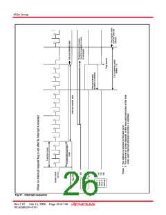
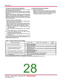
(4) Internal state during an interrupt
The internal state of the microcomputer during an interrupt is as
follows (Figure 25).
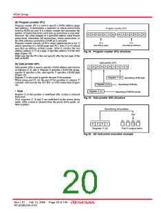
• Program counter (PC)
An interrupt address is set in program counter. The address to
be executed when returning to the main routine is
automatically stored in the stack register (SK).
• Interrupt enable flag (INTE)
• Program counter (PC)
• Stack register (SK)
Each interrupt address
The address of main routine to be
executed when returning
• Interrupt enable flag (INTE)
INTE flag is cleared to “0” so that interrupts are disabled.
• Interrupt request flag
Only the request flag for the current interrupt source is cleared
to “0”.
0 (Interrupt disabled)
• Interrupt request flag (only the flag for the current interrupt
source)
0
• Data pointer, carry flag, skip flag, registers A and B
The contents of these registers and flags are stored
automatically in the interrupt stack register (SDP).
• Data pointer, carry flag, registers A and B, skip flag
Stored in the interrupt stack register (SDP)
automatically
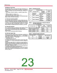
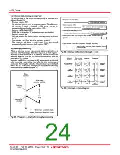
(5) Interrupt processing
When an interrupt occurs, a program at an interrupt address is
executed after branching a data store sequence to stack register.
Write the branch instruction to an interrupt service routine at an
interrupt address. Use the RTI instruction to return from an
interrupt service routine.
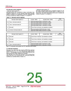
Fig 25. Internal state when interrupt occurs
Activated
condition
Request flag
(state retained)
Enable bit
Enable flag
Interrupt enabled by executing the EI instruction is performed
after executing 1 instruction (just after the next instruction is
executed). Accordingly, when the EI instruction is executed just
before the RTI instruction, interrupts are enabled after returning
the main routine. (Refer to Figure 24)
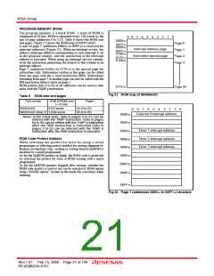
Address 0
in page 1
INT pin interrupt
waveform input
EXF0
T1F
V10
V12
V13
V20
Timer 1
underflow
Address 4
in page 1
Main
routine
Timer 2
underflow
Address 6
in page 1
T2F
Interrupt
service routine
Timer 3
underflow
Address 8
in page 1
T3F
INTE
Interrupt
occurs
Fig 26. Interrupt system diagram
EI
RTI
Interrupt is
enabled
: Interrupt enabled state
: Interrupt disabled state
Fig 24. Program example of interrupt processing
Rev.1.01 Feb 15, 2008 Page 24 of 146
REJ03B0224-0101

 RENESAS [ RENESAS TECHNOLOGY CORP ]