MULTIJUNCTION TIMERS
10.5 TMS (Input-Related 16-Bit Timer)
10
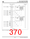
10.5.7 Operation of TMS Measure Input
(1) Outline of TMS measure input
In TMS measure input, when the timer is enabled (by writing to the enable bit in software), it starts counting
up synchronously with the count clock. Then when event input to TMS is detected while the timer is operat-
ing, the counter value is latched into measure registers 0–3. The timer stops counting at the same time count
is disabled by writing to the enable bit.
A TIN interrupt request can be generated by measure signal input from an external device. A TMS interrupt
request can be generated when the counter overflows.
Measure
event 0
occurs
Measure
event 1
occurs
Enabled
(by writing to the
enable bit)
Measure Measure
event 0
occurs
event 1 Overflow
occurs occurs
Count clock
Enable bit
H'FFFF
H'D000
H'C000
Counter
H'8000
H'6000
Undefined
value
H'0000
Undefined
Undefined
H'8000
H'6000
Measure 0 register
TIN15 interrupt request
H'D000
Measure 1 register
H'C000
TIN14 interrupt request
TMS interrupt request
due to overflow
Note: • This diagram does not show detailed timing information.
Figure 10.5.3 Typical Operation of TMS Measure Input
(2) Precautions on using TMS measure input
The following describes precautions to be observed when using TMS measure input.
• If measure event input and write to the counter occur in the same clock period, the write value is set in the
counter while at the same time latched into the measure register.
32180 Group User’s Manual (Rev.1.0)
10-131

 RENESAS [ RENESAS TECHNOLOGY CORP ]