MULTIJUNCTION TIMERS
10.6 TML (Input-Related 32-Bit Timer)
10
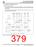
10.6.2 Outline of TML Operation
In TML, the timer starts counting upon deassertion of the reset input signal. The counter included in the timer is
a 32-bit up-counter, where when a measure event signal is entered from an external device, the counter value at
that point in time is stored in each 32-bit measure register.
When the reset input signal is deasserted, the counter starts operating with a BCLK/2 clock, and cannot be
stopped once it has started. The counter is idle only when the microcomputer remains reset.
A TIN interrupt request can be generated by external measure signal input. However, no TML counter overflow
interrupts are available.
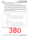
10.6.3 TML Related Register Map
Shown below is a TML related register map.
TML Related Register Map
Address
H'0080 03E0
H'0080 03E2
|
+0 address
+1 address
(Upper)
See pages
10-135
b0
b7 b8
TML0 Counter
(TML0CT)
b15
(Lower)
H'0080 03EA
(Use inhibited area)
TML0 Control Register
(TML0CR)
10-134
10-135
10-135
10-135
10-135
|
(Use inhibited area)
H'0080 03F0
H'0080 03F2
H'0080 03F4
H'0080 03F6
H'0080 03F8
H'0080 03FA
H'0080 03FC
H'0080 03FE
|
TML0 Measure 3 Register
(TML0MR3)
(Upper)
(Lower)
(Upper)
(Lower)
(Upper)
(Lower)
(Upper)
(Lower)
TML0 Measure 2 Register
(TML0MR2)
TML0 Measure 1 Register
(TML0MR1)
TML0 Measure 0 Register
(TML0MR0)
H'0080 0FE0
TML1 Counter
(TML1CT)
(Upper)
(Lower)
10-135
H'0080 0FE2
|
(Use inhibited area)
H'0080 0FEA
(Use inhibited area)
TML1 Control Register
(TML1CR)
10-134
10-135
10-135
10-135
10-135
|
(Use inhibited area)
H'0080 0FF0
H'0080 0FF2
H'0080 0FF4
H'0080 0FF6
H'0080 0FF8
H'0080 0FFA
H'0080 0FFC
H'0080 0FFE
TML1 Measure 3 Register
(TML1MR3)
(Upper)
(Lower)
(Upper)
(Lower)
(Upper)
(Lower)
(Upper)
(Lower)
TML1 Measure 2 Register
(TML1MR2)
TML1 Measure 1 Register
(TML1MR1)
TML1 Measure 0 Register
(TML1MR0)
32180 Group User’s Manual (Rev.1.0)
10-133

 RENESAS [ RENESAS TECHNOLOGY CORP ]