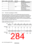
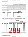
Bits 4 and 3—Area 2 Wait Control (A2W1, A2W0): Specify the number of wait states inserted
in physical space area 2.
•
For Ordinary Memory
Description
Bit 4: A2W0
Bit 3: A2W0
Inserted Wait States
WAIT Pin
0
0
1
0
1
0
1
2
3
Ignored
Enabled
1
Enabled
Enabled (Initial value)
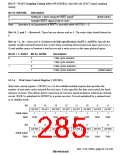
•
For Synchronous DRAM
Description
Bit 4: A2W1
Bit 3: A2W0
Synchronous DRAM: CAS Latency
0
0
1
0
1
1
1
2
1
3
(Initial value)
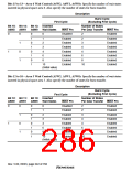
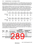
Bits 2 to 0—Area 0 Wait Control (A0W2, A0W1, A0W0): Specify the number of wait states
inserted in physical space area 0. Also specify the burst pitch for burst transfer.
Description
Burst Cycle
First Cycle
(Excluding First Cycle)
Number of States
Per Data Transfer WAIT Pin
Bit 2:
Bit 1:
Bit 0:
Inserted
A0W2
A0W1
A0W0
Wait States
WAIT Pin
Ignored
Enabled
Enabled
Enabled
Enabled
Enabled
Enabled
Enabled
0
0
1
0
1
0
1
0
1
0
1
0
1
0
1
2
3
4
6
8
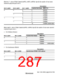
2
Enabled
Enabled
Enabled
Enabled
Enabled
Enabled
Enabled
Enabled
2
3
4
1
4
6
8
10
10
(Initial value)
Rev. 5.00, 09/03, page 244 of 760

 RENESAS [ RENESAS TECHNOLOGY CORP ]