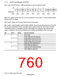
17.2.4 Serial Status Register (SCSSR1)
Bit 4 of SCSSR1 has a different function in smart card interface mode. Coupled with this, the
setting conditions for bit 2 (TEND) are also different.
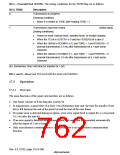
Bit:
7
6
5
4
3
2
1
0
TDRE
RDRF
ORER
FER/
ERS
PER
TEND
—
—
Initial value:
1
0
0
0
0
1
0
0
R/W: R/(W)* R/(W)* R/(W)* R/(W)* R/(W)*
Note: * Only 0 can be written, to clear the flag.
R
R
R/W
Bits 7 to 5: Operate in the same way as for the normal SCI. See section 15, Serial Communication
Interface (SCI), for details.
Bit 4—Error Signal Status (ERS): In smart card interface mode, bit 4 indicates the status of the
error signal sent back from the receiving side during transmission. Framing errors are not detected
in smart card interface mode.
Bit 4: ERS
Description
0
Normal reception, no error signal
[Clearing conditions]
(Initial value)
•
•
Power-on reset, manual reset, standby mode, or module standby
When 0 is written to ERS after reading ERS = 1
1
An error signal has been sent from the receiving side indicating detection of
a parity error
[Setting condition]
•
When the low level of the error signal is detected
Note: Clearing the TE bit in SCSCR1 to 0 does not affect the ERS flag, which retains its previous
state.
Bit 3—Parity Error (PER): Operates in the same way as for the normal SCI. See section 15,
Serial Communication Interface (SCI), for details.
Rev. 6.0, 07/02, page 709 of 986

 RENESAS [ RENESAS TECHNOLOGY CORP ]