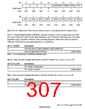
Bit:
15
—
14
—
13
—
12
—
0
11
10
9
8
CKOEN PLL1EN PLL2EN IFC2
Initial value:
R/W:
0
0
0
1
1
1
—
R/W
R/W
R/W
R
R/W
R/W
R/W
R/W
Bit:
7
6
5
4
3
2
1
0
IFC1
—
IFC0
—
BFC2
—
BFC1
—
BFC0
—
PFC2
—
PFC1
—
PFC0
—
Initial value:
R/W:
R/W
R/W
R/W
R/W
R/W
R/W
R/W
R/W
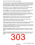
Bits 15 to 12—Reserved: These bits are always read as 0, and should only be written with 0.
Bit 11—Clock Output Enable (CKOEN): Specifies whether a clock is output from the CKIO
pin or the CKIO pin is placed in the high-impedance state. When the CKIO pin goes to the high-
impedance state, operation continues at the operating frequency before this state was entered.
When the CKIO pin becomes high-impedance, it is pulled up.
Bit 11: CKOEN
Description
0
1
CKIO pin goes to high-impedance state (pulled up*)
Clock is output from CKIO pin
(Initial value)
Note: * It is not pulled up in hardware standby mode.
Bit 10—PLL Circuit 1 Enable (PLL1EN): Specifies whether PLL circuit 1 is on or off.
Bit 10: PLL1EN
Description
0
1
PLL circuit 1 is not used
PLL circuit 1 is used
(Initial value)
Bit 9—PLL Circuit 2 Enable (PLL2EN): Specifies whether PLL circuit 2 is on or off.
Bit 9: PLL2EN
Description
0
1
PLL circuit 2 is not used
PLL circuit 2 is used
(Initial value)
Rev. 6.0, 07/02, page 255 of 986

 RENESAS [ RENESAS TECHNOLOGY CORP ]