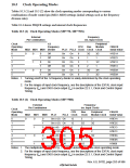
10.5
Changing the Frequency
There are two methods of changing the internal clock frequency: by changing stopping and
starting of PLL circuit 1, and by changing the frequency division ratio of each clock. In both
cases, control is performed by software by means of the frequency control register. These methods
are described below.
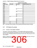
10.5.1 Changing PLL Circuit 1 Starting/Stopping (When PLL Circuit 2 is Off)
When PLL circuit 1 is changed from the stopped to started state, a PLL stabilization time is
required. The oscillation stabilization time count is performed by the on-chip WDT.
1. Set a value in WDT to provide the specified oscillation stabilization time, and stop the WDT.
The following settings are necessary:
WTCSR register TME bit = 0: WDT stopped
WTCSR register CKS2–CKS0 bits: WDT count clock division ratio
WTCNT counter: Initial counter value
2. Set the PLL1EN bit to 1.
3. Internal processor operation stops temporarily, and the WDT starts counting up. The internal
clock stops and an unstable clock is output to the CKIO pin.
4. After the WDT count overflows, clock supply begins within the chip and the processor
resumes operation. The WDT stops after overflowing.
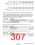
10.5.2 Changing PLL Circuit 1 Starting/Stopping (When PLL Circuit 2 is On)
When PLL circuit 2 is on, a PLL circuit 1 and PLL circuit 2 oscillation stabilization time is
required.
1. Make WDT settings as in 10.5.1.
2. Set the PLL1EN bit to 1.
3. Internal processor operation stops temporarily, PLL circuit 1 oscillates, and the WDT starts
counting up. The internal clock stops and an unstable clock is output to the CKIO pin.
4. After the WDT count overflows, PLL circuit 2 starts oscillating. The WDT resumes its up-
count from the value set in step 1 above. During this time, also, the internal clock is stopped
and an unstable clock is output to the CKIO pin.
5. After the WDT count overflows, clock supply begins within the chip and the processor
resumes operation. The WDT stops after overflowing.
Rev. 6.0, 07/02, page 257 of 986

 RENESAS [ RENESAS TECHNOLOGY CORP ]