CENTRAL PROCESSING UNIT (CPU)
2.1 Central processing unit (CPU)
2.1.9 Processor status register (PS)
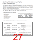
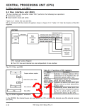
PS is an 11-bit register.
Figure 2.1.6 shows the structure of PS. Refer to “7900 Series Software Manual” for detale about the
change of each bit.
b15 b14 b13 b12 b11 b10 b9 b8 b7 b6 b5 b4 b3 b2 b1 b0
Processor status register
0
0
0
0
0
IPL
N
V
m
x
D
I
Z
C
(PS)
Note: Be sure to fix bits 15 through 11 to “0.”
Fig. 2.1.6 Structure of PS
(1) Bit 0: Carry flag (C)
This flag retains a carry or a borrow generated in the arithmetic and logic unit (ALU) during an
arithmetic operation. This flag is also affected by shift and rotate instructions.
Be sure to use the SEC or SEP instruction to set this flag to “1”; and be sure to use the CLC or CLP
instruction to clear it to “0”.
The contents of this flag is undefined at reset.
(2) Bit 1: Zero flag (Z)
This flag is set to “1” when the result of an arithmetic operation or data transfer is “0,” and cleared
to “0” when otherwise. This flag is invalid in the decimal arithmetic operation.
Be sure to use the SEP instruction to set this flag to “1”; and be sure to use the CLP instruction to
clear it to “0.”
The contents of this flag is undefined at reset.
(3) Bit 2: Interrupt disable flag (I)
This flag disables all maskable interrupts except the following: the address matching detection,
watchdog timer, and 0 division interrupts. Interrupts are disabled when this flag is “1.” When an
interrupt request has been accepted, this flag is automatically set to “1,” and multiple interrupts
become disabled. Be sure to use the SEI or SEP instruction to set this flag to “1”; and be sure to
use the CLI or CLP instruction to clear this flag to “0.”
This flag is set to “1” at reset.
(4) Bit 3: Decimal mode flag (D)
This flag determines whether addition and subtraction are performed in binary or decimal. Binary
arithmetic operation is performed when this flag is “0.” When it is “1,” decimal arithmetic operation
is performed with each 8 bits treated as 2-digit decimal (at m = 1) or each 16 bits treated as 4-digit
decimal (at m = 0). Decimal adjust is automatically performed. Decimal operation is possible only
with the ADC, ADCB, SBC and SBCB instructions. Be sure to use the SEP instruction to set this
flag to “1”; and be sure to use the CLP instruction to clear it to “0.”
This flag is cleared to “0” at reset.
(5) Bit 4: Index register length flag (x)
This flag determines whether each of index register X and index register Y is used as a 16-bit
register or an 8-bit register. That register is used as a 16-bit register when this flag is “0,” and as
an 8-bit register when it is “1” (Note). Be sure to use the SEP instruction to set this flag to “1”; and
be sure to use the CLP instruction to clear it to “0.”
This flag is cleared to “0” at reset.
7906 Group User’s Manual Rev.2.0
2-8

 RENESAS [ RENESAS TECHNOLOGY CORP ]