CENTRAL PROCESSING UNIT (CPU)
2.2 Bus interface unit (BIU)
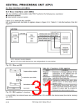
2.2.1 Instruction prefetch
While the CPU does not use the internal buses, the BIU reads instructions from the memory and then
stores them in the instruction queue buffer. The CPU reads instructions from the instruction queue buffer
and executes them, so that the CPU can operate at high speed without access to the memory, which
requires a long access time.
The instruction queue buffer can store instructions up to 10 bytes. The contents of the instruction queue
buffer is initialized when a branch is made, and the BIU reads a new instruction from the branch destination
address.
When instructions in the instruction queue buffer are insufficient for the CPU’s needs, the BIU extends the
low-level duration of φCPU (See Figure 4.2.1.) in order to keep the CPU waiting until the BIU fetches
instructions of the required byte number or more.
Figure 2.2.3 shows operating waveform examples
Table 2.2.2 Store address of prefetched instruction
Low-order 3 bits
at instruction prefetch. Note that the operation of
BIU’s instruction prefetch also varies with the store
addresses of instructions. Table 2.2.2 lists the store
address of prefetched instructions.
When the instruction prefetch from internal memory,
the instructions are fetched from 4-byte boundaries,
4 bytes at a time. (See Figure 2.2.3.)
at store address
AD
2
AD
1
AD
0
0
Even-numbered address
4-byte boundaries
8-byte boundaries
ꢀ
ꢀ
0
ꢀ
0
0
Also, at branch, regardless of the low-order 2 bits’
0
0
contents (AD
1
and AD ) of the branch destination
0
X: It may be either “0” or “1.”
address, 4 bytes are fetched at time from the 4-
byte boundaries. (See Figure 2.2.3.) In this case,
out of the data (instructions) which will be output onto the internal code buses, 4 bytes at a time, the
instructions assigned at the branch destination address and the following addresses will be fetched into the
instruction queue buffer. Accordingly, as listed in Table 2.2.3, the number of bytes to be fetched into the
instruction queue buffer varies according to the branch destination address.
Table 2.2.3 Number of bytes to be fetched into instruction queue buffer
Number of bytes to be
Low-order 2 bits of address to be
output onto address bus
Low-order 2 bits of branch destination
address
fetched into instruction
queue buffer
AD
0
1
AD
0
0
AD
0
1
AD
0
0
4
3
2
1
0
1
0
0
1
0
0
0
1
1
0
0
φBIU
Internal address bus
(AD –AD23
Address
0
)
Internal code bus
(CB –CB31
Data
(instruction)
0
)
φBIU: Operation clock of BIU (Refer to “CHAPTER 4. CLOCK GENERATING CIRCUIT.”)
Note: This waveform applies when bus cycle = 2φ. For details of the bus cycle at access to the internal area,
see Table 2.2.4.
Fig. 2.2.3 Operation waveform examples at instruction prefetch
7906 Group User’s Manual Rev.2.0
2-11

 RENESAS [ RENESAS TECHNOLOGY CORP ]