PULSE OUTPUT PORT MODE
9.3 Block description of pulse output port 1
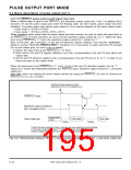
(4) Waveform output control bits 1, 0 (bits 7, 6)
These bits are used to control the waveform output of pulse output port 1. Table 9.3.3 lists the functions of
waveform output control bits 1, 0.
When a falling edge is input to pin P4OUTCUT, waveform output control bit 1 (bit 7) becomes “0.” (See Table
9.3.7.)
Table 9.3.3 Functions of waveform output control bits 1, 0
01
10
b2 b1 b0
00
11
P4
P4
P4
P4
7
6
5
4
/RTP3
3
2
1
0
P4
P4
P4
P4
7
6
5
4
/RTP3
3
2
1
0
P4
P4
P4
P4
7
6
5
4
/RTP3
3
2
1
0
P4
P4
P4
P4
7
6
5
4
/RTP3
3
2
1
0
Pulse mode 0
Pulse
output
enabled
Pulse
output
enabled
Floating
state
/RTP3
/RTP3
/RTP3
/RTP3
/RTP3
/RTP3
/RTP3
/RTP3
/RTP3
/RTP3
/RTP3
/RTP3
Floating
state
P4
3
2
1
0
/RTP2
/RTP2
/RTP2
/RTP2
3
2
1
0
P4
P4
P4
P4
3
2
1
0
/RTP2
/RTP2
/RTP2
/RTP2
3
2
1
0
P4
P4
P4
P4
3
2
1
0
/RTP2
/RTP2
/RTP2
/RTP2
3
2
1
0
P4
P4
P4
P4
3
2
1
0
/RTP2
/RTP2
/RTP2
/RTP2
3
2
1
0
Pulse
output
enabled
Pulse
output
enabled
Floating P4
Floating
state
state
P4
P4
Pulse
Pulse
output
enabled
P4
P4
7
/RTP3
/RTP3
3
P4
P4
7
6
/RTP3
/RTP3
3
2
P4
P4
7
6
/RTP3
/RTP3
3
2
Floating
state
P4
P4
7
6
/RTP3
/RTP3
3
2
Pulse mode 1
Floating
state
output
6
2
enabled
P4
P4
P4
P4
P4
P4
5
4
3
2
1
0
/RTP3
/RTP3
/RTP2
/RTP2
/RTP2
/RTP2
1
0
3
2
1
0
P4
P4
P4
P4
P4
P4
5
4
3
2
1
0
/RTP3
/RTP3
/RTP2
/RTP2
/RTP2
/RTP2
1
0
3
2
1
0
P4
P4
P4
P4
P4
P4
5
4
3
2
1
0
/RTP3
/RTP3
/RTP2
/RTP2
/RTP2
/RTP2
1
0
3
2
1
0
P4
P4
P4
P4
P4
P4
5
4
3
2
1
0
/RTP3
/RTP3
/RTP2
/RTP2
/RTP2
/RTP2
1
0
3
2
1
0
Pulse
output
enabled
Pulse
output
enabled
Floating
state
Floating
state
7905 Group User’s Manual Rev.1.0
9-18

 RENESAS [ RENESAS TECHNOLOGY CORP ]