VRS51C1000
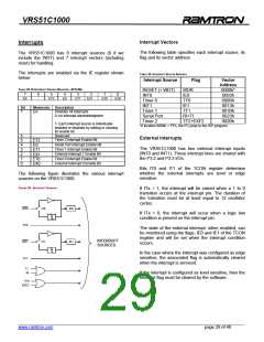
Interrupt Vectors
Interrupts
The following table specifies each interrupt source, its
flag and its vector address.
The VRS51C1000 has 8 interrupt sources (9 if we
include the WDT) and 7 interrupt vectors (including
reset) for handling.
The interrupts are enabled via the IE register shown
below:
TABLE 33: INTERRUPT VECTOR ADDRESS
Interrupt Source
Flag
Vector
Address
0000h*
0003h
000Bh
0013h
001Bh
0023h
002Bh
TABLE 32: IE INTERRUPT ENABLE REGISTER –SFR A8H
RESET (+ WDT)
INT0
WDR
IE0
7
EA
6
-
5
ET2
4
ES
3
ET1
2
EX1
1
ET0
0
EX0
Timer 0
TF0
INT1
IE1
Bit
Mnemonic Description
Timer 1
TF1
7
EA
Disables All Interrupts
0: no interrupt acknowledgment
Serial Port
Timer 2
RI+TI
TF2+EXF2
1: Each interrupt source is individually
enabled or disabled by setting or clearing
its enable bit.
*If location 0000h = FFh, the PC jump to the ISP program.
6
5
4
3
2
1
0
-
Reserved
Timer 2 Interrupt Enable Bit
External Interrupts
ET2
ES
ET1
EX1
ET0
EX0
Serial Port Interrupt Enable Bit
Timer 1 Interrupt Enable Bit
External Interrupt 1 Enable Bit
Timer 0 Interrupt Enable Bit
External Interrupt 0 Enable Bit
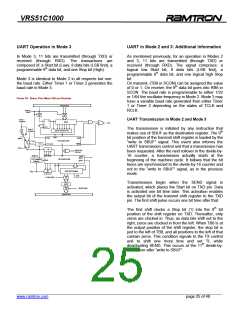
The VRS51C1000 has two external interrupt inputs
(INT0 and INT1). These interrupt lines are shared with
the P3.2 and P3.3 I/Os.
Bits IT0 and IT1 of the TCON register determine
whether the external interrupts are level or edge
sensitive.
The following figure illustrates the various interrupt
sources on the VRS51C1000.
FIGURE 20: INTERRUPT SOURCES
If ITx = 1, the interrupt will be raised when a 1 to 0
transition occurs at the interrupt pin. The duration of
the transition must be at least equal to 12 oscillator
cycles.
INT0
TF0
IT0
IE0
If ITx = 0, the interrupt will occur when a logic low
condition is present on the interrupt pin.
The state of the external interrupt, when enabled, can
be monitored using the flags, IE0 and IE1 of the TCON
register and will be set when the interrupt condition
occurs.
INTERRUPT
SOURCES
INT1
TF1
IT1
IE1
In the case where the interrupt was configured as edge
sensitive, the associated flag is automatically cleared
when the interrupt is serviced.
T1
RI
If the interrupt is configured as level sensitive, then the
interrupt flag must be cleared by the software.
TF2
EXF2
______________________________________________________________________________________________
www.ramtron.com page 29 of 48

 RAMTRON [ RAMTRON INTERNATIONAL CORPORATION ]