VRS51C1000
Timer 0 and Timer 1 Interrupt
Execution of an Interrupt
Both Timer 0 and Timer 1 can be configured to
When the processor receives an interrupt request, an
automatic jump to the desired subroutine occurs. This
jump is similar to executing a branch to a subroutine
instruction: the processor automatically saves the
address of the next instruction on the stack. An internal
flag is set to indicate that an interrupt is taking place,
and then the jump instruction is executed. An interrupt
subroutine must always end with the RETI instruction.
This instruction allows users to retrieve the return
address placed on the stack.
generate an interrupt when
a
rollover of the
timer/counter occurs (except Timer 0 in Mode 3).
The TF0 and TF1 flags serve to monitor timer overflow
occurring in Timer 0 and Timer 1. These interrupt flags
are automatically cleared when the interrupt is
serviced.
Timer 2 interrupt
The RETI instruction also allows updating of the
internal flag that will take into account an interrupt with
the same priority.
A Timer 2 interrupt can occur if TF2 and/or EXF2 flags
are set to 1 and if the Timer 2 interrupt is enabled.
The TF2 flag is set when a rollover of the Timer 2
Counter/Timer occurs. The EXF2 flag can be set by a
1 to 0 transition on the T2EX pin by the software.
Interrupt Enable and Interrupt Priority
When the VRS51C1000 is initialized, all interrupt
sources are inhibited by the bits of the IE register being
reset to 0. It is necessary to start by enabling the
interrupt sources that the application requires. This is
achieved by setting bits in the IE register, as discussed
previously.
Note that neither flag is cleared by the hardware upon
execution of the interrupt service routine. The service
routine may have to determine whether it was TF2 or
EXF2 that generated the interrupt. These flag bits will
have to be cleared by the software.
Every bit that generates interrupts can either be
cleared or set by the software, yielding the same result
as when the operation is done by the hardware. In
other words, pending interrupts can be cancelled and
interrupts can be generated by the software.
This register is part of the bit addressable internal
SRAM. For this reason, it is possible to modify each bit
individually in one instruction without having to modify
the other bits of the register. All interrupts can be
inhibited by setting EA to 0.
The order in which interrupts are serviced is shown in
the following table:
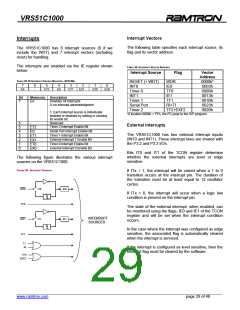
Serial Port Interrupt
The serial port can generate an interrupt upon byte
reception or once the byte transmission is completed.
TABLE 34: INTERRUPT PRIORITY
Interrupt Source
RESET + WDT (Highest Priority)
IE0
TF0
IE1
Those two conditions share the same interrupt vector
and it is up to the user developed interrupt service
routine software to ascertain the cause of the interrupt
by looking at the serial interrupt flags RI and TI.
TF1
RI+TI
Note that neither of these flags are cleared by the
hardware upon execution of the interrupt service
routine. The software must clear these flags.
TF2+EXF2 (Lowest Priority)
______________________________________________________________________________________________
www.ramtron.com page 30 of 48

 RAMTRON [ RAMTRON INTERNATIONAL CORPORATION ]