VRS51C1000
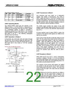
UART Reception in Mode 2 and Mode 3
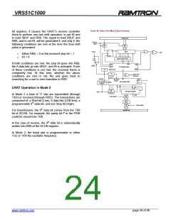
UART Baud Rates
In Mode 0, the baud rate is fixed and can be
represented by the following formula:
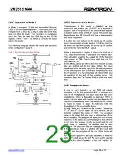
One to zero transitions on the RXD pin initiate
reception. It is for this reason that RXD is sampled at a
rate of 16 multiplied by the baud rate that has been
established.
When a transition is detected, the 1FFh is written into
the input shift register and the divide-by-16 counter is
immediately reset.
Mode 0 Baud Rate = Oscillator Frequency
12
During the 7th, 8th and 9th counter states of each bit
time; the bit detector samples the value of RXD. The
accepted value is the value that was seen in at least
two of the three samples. If the value accepted during
the first bit time is not zero, the receive circuits are
reset and the unit goes back to searching for another
one to zero transition. If the start bit is valid, it is shifted
into the input shift register, and the reception of the
rest of the frame will proceed.
In Mode 2, the baud rate depends on the value of the
SMOD bit in the PCON SFR. From the formula below,
we can see that if SMOD = 0 (which is the value on
reset), the baud rate is 1/32 the oscillator frequency.
Mode 2 Baud Rate = 2SMOD x (Oscillator Frequency)
64
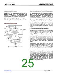
For a receive operation, the data bits come in from the
right as 1’s shift out on the left. As soon as the start bit
arrives at the leftmost position in the shift register (9-bit
register), it tells the RX control block to do one more
shift, to set RI, and to load SBUF and RB8. The signal
to set RI and to load SBUF and RB8 will be generated
if, and only if, the following conditions are satisfied at
the instance when the final shift pulse is generated:
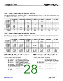
The Timer 1 and/or Timer 2 overflow rate determines
the baud rates in Modes 1 and 3.
Generating UART Baud Rate with Timer 1
Either SM2 = 0 or the received 9th bit equal 1
RI = 0
When Timer 1 functions as a baud rate generator, the
baud rate in Modes 1 and 3 are determined by the
Timer 1 overflow rate.
-
-
If both conditions are met, the 9th data bit received
goes into RB8, and the first 8 data bits go into SBUF. If
one of these conditions is not met, the received frame
is completely lost. One bit time later, whether the
above conditions are met or not, the unit goes back to
searching for a one to zero transition at the RXD input.
Please note that the value of the received stop bit is
unrelated to SBUF, RB8 or RI.
Mode 1,3 Baud Rate = 2SMODx Timer 1 Overflow Rate
32
Timer 1 must be configured as an 8-bit timer (TL1) with
auto-reload with TH1 value when an overflow occurs
(Mode 2). In this application, the Timer 1 interrupt
should be disabled.
The two following formulas can be used to calculate
the baud rate and the reload value to be written into
the TH1 register.
Mode 1,3 Baud Rate =
2
SMODx Fosc
32 x 12(256 – TH1)
______________________________________________________________________________________________
www.ramtron.com page 26 of 48

 RAMTRON [ RAMTRON INTERNATIONAL CORPORATION ]