©Quantum Research Group Ltd.
The threshold is user-programmed using the setup process
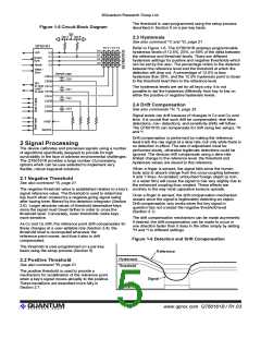
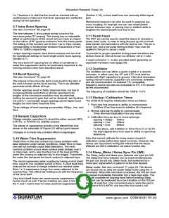
Figure 1-5 Circuit Block Diagram
described in Section 5 on a per-key basis.
Vcc
Opt A
Opt B
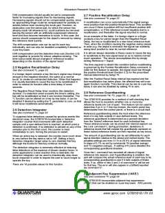
2.3 Hysteresis
See also command ^C and ^D, page 21
QT60161
Y0 Y1 Y2 Y3
Refer to Figure 1-6. The QT60161B employs programmable
hysteresis levels of 12.5%, 25%, or 50% of the delta between
the reference and threshold levels. There are different
hysteresis settings for positive and negative thresholds which
can be set by the user. The percentage refers to the distance
between the reference level and the threshold at which the
detection will drop out. A percentage of 12.5% is less
hysteresis than 25%, and the 12.5% hysteresis point is closer
to the threshold level than to the reference level.
X0
X1
X2
X3
LED
X0
X1
X2
X3
Scope
Sync
Reset
Wake /
Sync
Sample caps
CS0
CS0A
CS0B
CS1A
CS1B
CS2A
CS2B
SPI
to Host
UART
to Host
The hysteresis levels are set for all keys only; it is not
possible to set the hysteresis differently from key to key on
either the positive or negative hysteresis levels.
CS1
CS2
2.4 Drift Compensation
See also commands ^H, ^I, page 22
CS3A
CS3B
CS3
Signal levels can drift because of changes in Cx and Cs over
time. It is crucial that such drift be compensated, else false
detections, non- detections, and sensitivity shifts will follow.
The QT60161B can compensate for drift using two setups, ^H
and ^I.
VREF
Sample
Drift compensation is performed by making the reference
level track the raw signal at a slow rate, but only while there is
no detection in effect. The rate of adjustment must be
performed slowly, otherwise legitimate detections could be
ignored. The devices drift compensate using a slew-rate
limited change to the reference level; the threshold and
hysteresis values are slaved to this reference.
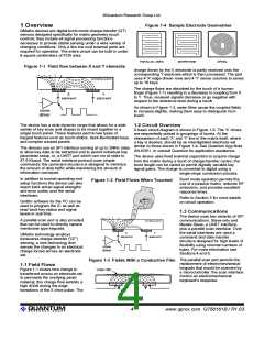
2 Signal Processing
The device calibrates and processes signals using a number
of algorithms specifically designed to provide for high
survivability in the face of adverse environmental challenges.
The QT60161B provides a large number of processing
options which can be user-selected to implement very
flexible, robust keypanel solutions.
When a finger is sensed, the signal falls since the human
body acts to absorb charge from the cross-coupling between
X and Y lines. An isolated, untouched foreign object (a coin,
or a water film) will cause the signal to rise very slightly due to
the enhanced coupling thus created. These effects are
2.1 Negative Threshold
See also command ^A, page 21
The negative threshold value is established relative to a key’s contrary to the way most capacitive sensors operate.
signal reference value. The threshold is used to determine
Once a finger is sensed, the drift compensation mechanism
key touch when crossed by a negative-going signal swing
ceases since the signal is legitimately detecting an object.
after having been filtered by the detection integrator (Section
Drift compensation only works when the key signal in
2.6). Larger absolute values of threshold desensitize keys
question has not crossed the negative threshold level
since the signal must travel farther in order to cross the
(Section 2.1).
threshold level. Conversely, lower thresholds make keys
more sensitive.
The drift compensation mechanism can be made asymmetric
if desired; the drift-compensation can be made to occur in
one direction faster than it does in the other simply by setting
^H and ^I to different settings.
As Cx and Cs drift, the reference point drift-compensates for
these changes at a user-settable rate (Section 2.4); the
threshold level is recomputed whenever the
reference point moves, and thus it also is drift
compensated.
Figure 1-6 Detection and Drift Compensation
The threshold is user-programmed on a per-key
basis using the setup process (Section 5).
Reference
Hysteresis
Threshold
2.2 Positive Threshold
See also command ^B, page 21
The positive threshold is used to provide a
mechanism for recalibration of the reference point
when a key's signal moves abruptly to the positive.
These transitions are described more fully in
Section 2.7.
Signal
Output
lQ
5
www.qprox.com QT60161B / R1.03

 QUANTUM [ QUANTUM RESEARCH GROUP ]