©Quantum Research Group Ltd.
Contents
5.3 Status Commands . . . . . . . . . . . . . . . . . . . . . . . . . . . . . . . 18
0x30 - Signal for Single Key
1 Overview . . . . . . . . . . . . . . . . . . . . . . . . . . . . . . . . . . . . . . . . . . . .
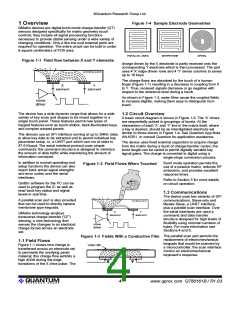
1.1 Field Flows . . . . . . . . . . . . . . . . . . . . . . . . . . . . . . . . . . . . . . .
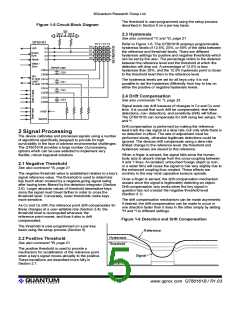
1.2 Circuit Overview . . . . . . . . . . . . . . . . . . . . . . . . . . . . . . . . . .
1.3 Communications . . . . . . . . . . . . . . . . . . . . . . . . . . . . . . . . . .
2 Signal Processing . . . . . . . . . . . . . . . . . . . . . . . . . . . . . . . . . . . .
2.1 Negative Threshold . . . . . . . . . . . . . . . . . . . . . . . . . . . . . . . .
2.2 Positive Threshold . . . . . . . . . . . . . . . . . . . . . . . . . . . . . . . . .
2.3 Hysteresis . . . . . . . . . . . . . . . . . . . . . . . . . . . . . . . . . . . . . . .
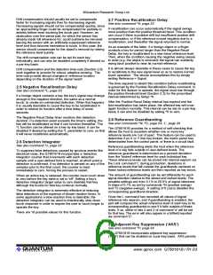
2.4 Drift Compensation . . . . . . . . . . . . . . . . . . . . . . . . . . . . . . . .
2.5 Negative Recalibration Delay . . . . . . . . . . . . . . . . . . . . . . . .
2.6 Detection Integrator . . . . . . . . . . . . . . . . . . . . . . . . . . . . . . . .
2.7 Positive Recalibration Delay . . . . . . . . . . . . . . . . . . . . . . . . .
2.8 Reference Guardbanding . . . . . . . . . . . . . . . . . . . . . . . . . . .
2.9 Adjacent Key Suppression (‘AKS’) . . . . . . . . . . . . . . . . . . . .
2.10 Full Recalibration . . . . . . . . . . . . . . . . . . . . . . . . . . . . . . . . .
2.11 Device Status & Reporting . . . . . . . . . . . . . . . . . . . . . . . . .
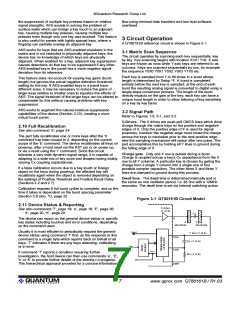
3 Circuit Operation . . . . . . . . . . . . . . . . . . . . . . . . . . . . . . . . . . . . .
3.1 Matrix Scan Sequence . . . . . . . . . . . . . . . . . . . . . . . . . . . . .
3.2 Signal Path . . . . . . . . . . . . . . . . . . . . . . . . . . . . . . . . . . . . . .
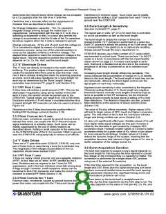
3.3 'X' Electrode Drives . . . . . . . . . . . . . . . . . . . . . . . . . . . . . . . .
4
4
4
4
5
5
5
5
5
6
6
6
6
6
7
7
7
7
7
8
8
8
8
8
8
8
8
9
9
9
9
9
9
9
9
0
. . . . . . . . . . . . . . . . . . . . . . . . . . 18
1
0x31 - Delta Signal for Single Key
. . . . . . . . . . . . . . . . . . . . . . . 18
. . . . . . . . . . . . . . . . . . . . . . . . . . . . . 18
2
5
6
0x32 - Reference Value
0x35 - Detection Integrator Counts
. . . . . . . . . . . . . . . . . . . . . . 18
. . . . . . . . . . . . . . . . . . . . . . . . . . . 18
. . . . . . . . . . . . . . . . . . . . . . . . . . 19
0x36 - Eeprom Checksum
7
0x37 - General Device Status
<sp> 0x20 - Signal Levels for Group
. . . . . . . . . . . . . . . . . . . . . . . 19
. . . . . . . . . . . . . . . . . . . . . . . . . 19
. . . . . . . . . . . . . . . . . . . . . . 19
!
0x21 - Delta Signals for Group
0x22 - Reference Levels for Group
"
%
e
E
k
0x25 - Detect Integrator Counts for Group
0x65 - Error Code for Selected Key
. . . . . . . . . . . . . . . . . 19
. . . . . . . . . . . . . . . . . . . . . . 19
0x45 - Error Codes for Group
. . . . . . . . . . . . . . . . . . . . . . . . . 20
. . . . . . . . . . . . . . . . . . . . 20
0x6B - Reporting of First Touched Key
5.4 Setup Commands . . . . . . . . . . . . . . . . . . . . . . . . . . . . . . 21
^A 0x01 - Negative Detect Threshold
. . . . . . . . . . . . . . . . . . . . . . . 21
^B 0x02 - Positive Detect Threshold
. . . . . . . . . . . . . . . . . . . . . . . 21
. . . . . . . . . . . . . . . . . . . . 21
. . . . . . . . . . . . . . . . . . . . . 21
^C 0x03 - Negative Threshold Hysteresis
^D 0x04 - Positive Threshold Hysteresis
^F 0x06 - Burst Length
. . . . . . . . . . . . . . . . . . . . . . . . . . . . . . . 21
. . . . . . . . . . . . . . . . . . . . . . . . . . . . . . 22
^G 0x07 - Burst Spacing
3.3.1 RFI From X Lines
. . . . . . . . . . . . . . . . . . . . . . . . . . . . . . . . . .
^H 0x08 - Negative Drift Compensation Rate5
3.3.2 Noise Coupling Into X lines
. . . . . . . . . . . . . . . . . 22
. . . . . . . . . . . . . . . . . . 22
. . . . . . . . . . . . . . . . . . . 22
. . . . . . . . . . . . . . . . . . . . . 23
. . . . . . . . . . . . . . . . . . . . . 23
. . . . . . . . . . . . . . . . . . . . . . . 23
. . . . . . . . . . . . . . . . . . . . . . . . . . . .
3.4 'Y' Gate Drives . . . . . . . . . . . . . . . . . . . . . . . . . . . . . . . . . . . .
^I 0x09 - Positive Drift Compensation Rate
^J 0x0A - Negative Detect Integrator Limit
3.4.1 RFI From Y Lines
. . . . . . . . . . . . . . . . . . . . . . . . . . . . . . . . . .
. . . . . . . . . . . . . . . . . . . . . . . . . . . .
^K 0x0B - Positive Recalibration Delay
3.4.2 Noise Coupling Into Y Lines
^L 0x0C - Negative Recalibration Delay
3.5 Burst Length & Sensitivity . . . . . . . . . . . . . . . . . . . . . . . . . . .
3.6 Burst Acquisition Duration . . . . . . . . . . . . . . . . . . . . . . . . . .
3.7 Intra-Burst Spacing . . . . . . . . . . . . . . . . . . . . . . . . . . . . . . . .
3.8 Burst Spacing . . . . . . . . . . . . . . . . . . . . . . . . . . . . . . . . . . . .
3.9 Sample Capacitors . . . . . . . . . . . . . . . . . . . . . . . . . . . . . . . .
3.10 Water Film Suppression . . . . . . . . . . . . . . . . . . . . . . . . . . .
3.11 Reset Input . . . . . . . . . . . . . . . . . . . . . . . . . . . . . . . . . . . . .
3.12 Oscillator . . . . . . . . . . . . . . . . . . . . . . . . . . . . . . . . . . . . . . .
3.13 Startup / Calibration Times . . . . . . . . . . . . . . . . . . . . . . . . .
3.14 Sleep_Wake / Noise Sync Pin (WS) . . . . . . . . . . . . . . . . .
^M 0x0D - Intra-Burst Pulse Spacing
^N 0x0E - Positive Reference Error Band
. . . . . . . . . . . . . . . . . . . . 23
. . . . . . . . . . . . . . . . . . . 23
. . . . . . . . . . . . . . . . . . 24
^O 0x0F - Negative Reference Error Band
^P 0x10 - Adjacent Key Suppression (‘AKS’)
5.5 Supervisory / System Functions . . . . . . . . . . . . . . . . . . . . 24
6
L
b
l
0x36 - Eeprom Checksum
0x4C - Lock Reference Levels
0x62 - Recalibrate Keys
. . . . . . . . . . . . . . . . . . . . . . . . . . . 24
. . . . . . . . . . . . . . . . . . . . . . . . . 24
. . . . . . . . . . . . . . . . . . . . . . . . . . . . . 24
0x6C - Return Last Command Character
. . . . . . . . . . . . . . . . . . . 25
. . . . . . . . . . . . . . . . . . . . . . . . . . . . . . . 25
r
0x72 - Reset Device
3.15 LED / Alert Output . . . . . . . . . . . . . . . . . . . . . . . . . . . . . . 10
3.16 Oscilloscope Sync . . . . . . . . . . . . . . . . . . . . . . . . . . . . . . 11
3.17 Power Supply & PCB Layout . . . . . . . . . . . . . . . . . . . . . 11
3.18 ESD / Noise Considerations . . . . . . . . . . . . . . . . . . . . . . 11
4 Communications Interfaces . . . . . . . . . . . . . . . . . . . . . . . . . . 11
4.1 Serial Protocol Overview . . . . . . . . . . . . . . . . . . . . . . . . . . 11
4.2 SPI Port Specifications . . . . . . . . . . . . . . . . . . . . . . . . . . . 12
4.3 SPI Slave-Only Mode . . . . . . . . . . . . . . . . . . . . . . . . . . . . 12
4.4 SPI Master-Slave Mode . . . . . . . . . . . . . . . . . . . . . . . . . . 13
4.5 UART Interface . . . . . . . . . . . . . . . . . . . . . . . . . . . . . . . . . 14
4.6 Sensor Echo and Data Response . . . . . . . . . . . . . . . . . . 15
4.7 Parallel Scan Port . . . . . . . . . . . . . . . . . . . . . . . . . . . . . . . 15
4.8 Eeprom Corruption . . . . . . . . . . . . . . . . . . . . . . . . . . . . . . 16
5 Commands & Functions . . . . . . . . . . . . . . . . . . . . . . . . . . . . . 17
5.1 Put / Get Direction Commands . . . . . . . . . . . . . . . . . . . . . 17
V
W
Z
0x56 - Return Part Version
0x57 - Return Part Signature
0x5A - Enter Sleep
. . . . . . . . . . . . . . . . . . . . . . . . . . . 25
. . . . . . . . . . . . . . . . . . . . . . . . . 25
. . . . . . . . . . . . . . . . . . . . . . . . . . . . . . . . 25
^Q 0x11 - Data Rate Selection
^R 0x12 - Oscilloscope Sync
^W 0x17 - Noise Sync
. . . . . . . . . . . . . . . . . . . . . . . . . . 25
. . . . . . . . . . . . . . . . . . . . . . . . . . . 26
. . . . . . . . . . . . . . . . . . . . . . . . . . . . . . . 26
5.6 Function Summary Table . . . . . . . . . . . . . . . . . . . . . . . . . 27
5.7 Timing Limitations . . . . . . . . . . . . . . . . . . . . . . . . . . . . . . 30
5.8 Erratta / Notes . . . . . . . . . . . . . . . . . . . . . . . . . . . . . . . . . 30
6 Electrical Specifications . . . . . . . . . . . . . . . . . . . . . . . . . . . . 31
6.1 Absolute Maximum Specifications . . . . . . . . . . . . . . . . . . 31
6.2 Recommended operating conditions . . . . . . . . . . . . . . . . 31
6.3 DC Specifications . . . . . . . . . . . . . . . . . . . . . . . . . . . . . . . 31
6.4 Protocol Timing . . . . . . . . . . . . . . . . . . . . . . . . . . . . . . . . . 31
6.5 Maximum Drdy Response Delays . . . . . . . . . . . . . . . . . . 32
7 Mechanical . . . . . . . . . . . . . . . . . . . . . . . . . . . . . . . . . . . . . . . . 33
7.1 Dimensions . . . . . . . . . . . . . . . . . . . . . . . . . . . . . . . . . . . . 33
7.2 Marking . . . . . . . . . . . . . . . . . . . . . . . . . . . . . . . . . . . . . . . 33
8 Index . . . . . . . . . . . . . . . . . . . . . . . . . . . . . . . . . . . . . . . . . . . . . 34
g
0x67 - Get Command
. . . . . . . . . . . . . . . . . . . . . . . . . . . . . . 17
. . . . . . . . . . . . . . . . . . . . . . . . . . . . . . 17
5.2 Scope Commands . . . . . . . . . . . . . . . . . . . . . . . . . . . . . . 18
p
0x70 - Put Command
s
0x73 - Specific Key Scope
. . . . . . . . . . . . . . . . . . . . . . . . . . . 18
. . . . . . . . . . . . . . . . . . . . . . . . . . . . . . 18
S
0x53 - All Keys Scope
x
0x78 - Row Keys Scope
. . . . . . . . . . . . . . . . . . . . . . . . . . . . . 18
0x79 - Column Keys Scope
. . . . . . . . . . . . . . . . . . . . . . . . . . . 18
y
lQ
ii
www.qprox.com QT60161B / R1.03

 QUANTUM [ QUANTUM RESEARCH GROUP ]