©Quantum Research Group Ltd.
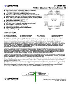
Figure 1-4 Sample Electrode Geometries
1 Overview
QMatrix devices are digital burst mode charge-transfer (QT)
sensors designed specifically for matrix geometry touch
controls; they include all signal processing functions
necessary to provide stable sensing under a wide variety of
changing conditions. Only a few low cost external parts are
required for operation. The entire circuit can be built in under
6 square centimeters of PCB area.
PARALLEL LINES
SERPENTINE
SPIRAL
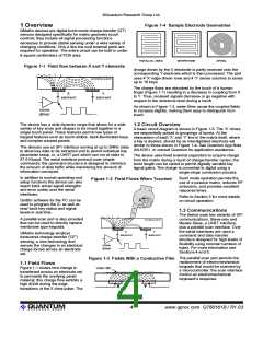
Figure 1-1 Field flow between X and Y elements
charge driven by the X electrode is partly received onto the
corresponding Y electrode which is then processed. The part
uses 4 'X' edge-driven rows and 4 'Y' sense columns to sense
up to 16 keys.
overlying panel
The charge flows are absorbed by the touch of a human
finger (Figure 1-1) resulting in a decrease in coupling from X
to Y. Thus, received signals decrease or go negative with
respect to the reference level during a touch.
X
Y
element
element
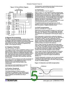
As shown in Figure 1-3, water films cause the coupled fields
to increase slightly, making them easy to distinguish from
touch.
The device has a wide dynamic range that allows for a wide
variety of key sizes and shapes to be mixed together in a
single touch panel. These features permit new types of
keypad features such as touch-sliders, back-illuminated keys,
and complex warped panels.
1.2 Circuit Overview
A basic circuit diagram is shown in Figure 1-5. The ‘X’ drives
are sequentially pulsed in groupings of bursts. At the
intersection of each ‘X’ and ‘Y’ line in the matrix itself, where
a key is desired, should be an interdigitated electrode set
similar to those shown in Figure 1-4. See Quantum App Note
AN-KD01, or consult Quantum for application assistance.
The devices use an SPI interface running at up to 3MHz rates
to allow key data to be extracted and to permit individual key
parameter setup, or, a UART port which can run at rates to
57.6 Kbaud. The serial interface protocol uses simple
commands; the command structure is designed to minimize
the amount of data traffic while maximizing the amount of
information conveyed.
The device uses fixed external capacitors to acquire charge
from the matrix during a burst of charge-transfer cycles; the
burst length can be varied to permit digitally variable key
signal gains. The charge is converted to digital using a
single-slope conversion process.
In addition to normal operating and
Burst mode operation permits the
use of a passive matrix, reduces RF
emissions, and provides excellent
response times.
Figure 1-2 Field Flows When Touched
setup functions the device can also
report back actual signal strengths
and error codes over the serial
interfaces.
Refer to Section 3 for more details
on circuit operation.
QmBtn software for the PC can be
used to program the IC as well as
read back key status and signal
levels in real time.
1.3 Communications
The device uses two variants of SPI
A parallel scan port is also provided
that can be used to directly replace
membrane type keypads.
overlying panel
communications, Slave-only and
Master-Slave, a UART interface,
plus a parallel scan interface. Over
the serial interfaces are used a
command and data transfer
structure designed for high levels of
flexibility using minimal numbers of
bytes. For more information see
Sections 4 and 5.
X
Y
QMatrix technology employs
transverse charge-transfer ('QT')
sensing, a new technology that
senses the changes in an electrical
charge forced across an electrode
set.
element
element
The parallel scan port permits the
replacement of electromechanical
keypads that would be scanned by
a microcontroller; the scan interface
mimics an electromechanical
keyboard’s response.
Figure 1-3 Fields With a Conductive Film
1.1 Field Flows
Figure 1-1 shows how charge is
transferred across an electrode set
to permeate the overlying panel
material; this charge flow exhibits a
high dQ/dt during the edge
transitions of the X drive pulse. The
lQ
4
www.qprox.com QT60161B / R1.03

 QUANTUM [ QUANTUM RESEARCH GROUP ]