©Quantum Research Group Ltd.
the suppression of multiple key presses based on relative flow using minimal data transfers and low host software
signal strengths. AKS assists in solving the problem of
surface water which can bridge a key touch to an adjacent
key, causing multiple key presses, causing multiple key
presses even though only one key was touched. This feature
is also useful for panels with tightly spaced keys, where a
fingertip can partially overlap an adjacent key.
overhead.
3 Circuit Operation
A QT60161B reference circuit is shown in Figure 2-1.
AKS works for keys that are AKS-enabled anywhere in the
matrix and is not restricted to physically adjacent keys; the
device has no knowledge of which keys are physically
adjacent. When enabled for a key, adjacent key suppression
causes detections on that key to be suppressed if any other
AKS-enabled key in the panel has a more negative signal
deviation from its reference.
3.1 Matrix Scan Sequence
The circuit operates by scanning each key sequentially, key
by key. Key scanning begins with location X=0 / Y=0. X axis
keys are known as rows while Y axis keys are referred to as
columns. Keys are scanned sequentially by row, for example
the sequence Y0X0 Y0X1 Y0X2 Y0X3 Y1X0 etc.
Each key is sampled from 1 to 64 times in a burst whose
length is determined by Setup ^F. A burst is completed
entirely before the next key is sampled; at the end of each
burst the resulting analog signal is converted to digital using a
single-slope conversion process. The length of the burst
directly impacts on the gain of the key; each key can have a
unique burst length in order to allow tailoring of key sensitivity
on a key by key basis.
This feature does not account for varying key gains (burst
length) but ignores the actual negative detection threshold
setting for the key. If AKS-enabled keys in a panel have
different sizes, it may be necessary to reduce the gains of
larger keys relative to smaller ones to equalize the effects of
AKS. The signal threshold of the larger keys can be altered to
compensate for this without causing problems with key
suppression.
AKS works to augment the natural moisture suppression
capabilities of the device (Section 3.10), creating a more
robust touch panel.
3.2 Signal Path
Refer to Figures 1-5, 3-1, and 3-2.
X-Drives. The X drives are push-pull CMOS lines which drive
charge through the matrix keys on the positive and negative
edges of X. Only the positive edge of X is used for signal
purposes, however the negative edge must cause the charge
across the keys to neutralize prior to the next positive edge,
else the sampling mechanism will cease after one pulse. The
part accomplishes this by holding all Y lines to ground during
the falling edge of X.
2.10 Full Recalibration
See also command ‘b’, page 24
The part fully recalibrates one or more keys after the ‘b’
command has been issued to it, depending on the current
scope of the ‘b’ command. The device recalibrates all keys on
powerup, after a hard reset via the RST pin or on power up,
or via a reset using the ‘r’ command. Since the circuit
tolerates a very wide dynamic signal range, it is capable of
adapting to a wide mix of key sizes and shapes having widely
varying Cx coupling capacitances.
Charge gate. Only one X row is pulsed during a burst.
Charge is coupled across a key's Cx capacitance from the X
row to all Y columns. A particular key is chosen by gating the
charge from a single Y column into a single one of four
possible sampler capacitors. The other three X and three Y
lines are clamped to ground during this process.
If a false calibration occurs due to a key touch or foreign
object on the keys during powerup, the affected key will
recalibrate again when the object is removed depending on
the settings of Positive Threshold and Positive Recal Delay
(Sections 2.2 and 2.7).
Dwell time. The dwell time is determined internally and is
the same as one oscillator period, i.e. 83.3ns with a 12MHz
resonator. The dwell time is set via internal switching action
Calibration requires 9 full burst cycles to complete, and so the
time it takes is dependent on the burst spacing parameter
(Section 3.8 also, ^G, page 22.
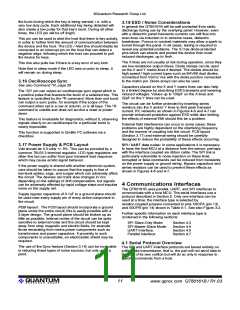
Figure 3-1 QT60161B Circuit Model
2.11 Device Status & Reporting
See also commands ‘7’, page 19; ‘e’, page 19; ‘E’, page 20;
‘k’, page 20, ‘K’, page 20
X drive
(1 of 4)
Cx
X
The device can report on the general device status or specific
key states including touches and error conditions, depending
on the command used.
X
Y
electrode
electrode
Usually it is most efficient to periodically request the general
device status using command ‘7’ first, as the response to this
command is a single byte which reports back on behalf of all
keys. ‘7’ indicates if there are any keys detecting, calibrating,
or in error.
Result
Y line (1 of 4)
Cs (1 of 4)
CSA
Start
CSB
SMP
Done
If command ‘7’ reports a condition requiring further
Rs (1 of 4)
investigation, the host device can then use commands ‘e’, ‘E’,
‘k’ or ‘K’ to provide further details of the event(s) in progress.
This hierarchical approach provides for a concise information
lQ
7
www.qprox.com QT60161B / R1.03

 QUANTUM [ QUANTUM RESEARCH GROUP ]