S/UNI®-ATLAS-3200 Telecom Standard Product Data Sheet
Preliminary
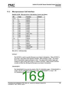
RESTART
The restart cell read (RESTART) bit resets the microprocessor cell read pointer. If RESTART
is set to logic 1 during a cell read, the next word read from the Microprocessor Cell Data
register will be the first word of the current cell. Subsequent reads from the Microprocessor
Cell Data register return the remaining words of the cell.
RESTART is not readable, and is cleared upon a read of the Microprocessor Cell Data
register. RESTART and ABORT should not be simultaneously asserted.
ABORT
The read abort (ABORT) bit allows the microprocessor to discard a cell without reading the
contents. If ABORT is logic 1, the current cell being read is purged from the extract FIFO
and the DMAREQ output will be deasserted.
ABORT is not readable, and is cleared upon a read of the Microprocessor Cell Data register.
ABORT and RESTART should not be simultaneously asserted.
EXTCA
The microprocessor cell available (EXTCA) status bit indicates that at least one cell is
present in the cell extract buffer. EXTCA is set to logic 1 when the last word of a cell is
received. EXTCA is cleared to logic 0 when the last word in the buffer is read by the
microprocessor. If multiple cells exist in the buffer, then EXTCA will remain at logic 1 until
the last word of the last cell is read.
Assertion of the EXTCA status bit also results in a maskable interrupt.
RSOC
The RSOC bit is logic 1 when the data in MCD[31:0] contains the first d-word (of 16) in a
cell. This word will be part of the Microprocessor Cell Info field if the Cell_Info_to_UP bit
is set in the CP Configuration Register.
Bits [31 16] Cell Insertion
INSRST
The INSRST bit is used to reset the Microprocessor Insert Cell Interface. When INSRST is
set to logic 0, the insert FIFO operates normally. When INSRST is set to logic 1, the insert
FIFO is immediately emptied and ignores writes. The insert FIFO remains empty and
continues to ignore writes until a logic 0 is written into INSRST.
Any transfer from the insert FIFO currently in progress will be aborted. While asserted,
INSRST overrides all other bits affecting the Microprocessor Insert Cell Interface.
Proprietary and Confidential to PMC-Sierra, Inc., and for its Customers’ Internal Use
Document ID: PMC-1990553, Issue 4
170

 PMC [ PMC-SIERRA, INC ]