PM6341 E1XC
DATA SHEET
PMC-910419
ISSUE 8
E1 FRAMER/TRANSCEIVER
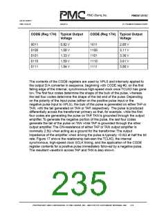
CODE (Reg 17H) Typical Output
Voltage
CODE (Reg 17H) Typical Output
Voltage
0011
0100
0101
0110
0111
0.82 V
1.08 V
1.33 V
1.59 V
1.84 V
1011
1100
1101
1110
1111
2.85 V
3.11 V
3.36 V
3.61 V
3.86 V
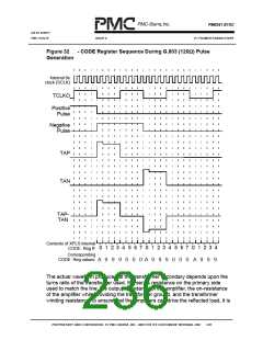
The contents of the CODE registers are used by XPLS and internally applied to
the output D/A converter in sequence, beginning with CODE reg #0, on the first
falling edge of the internal, synchronous high-speed clock once TCLKO has gone
low.The first four codes determine the shape of the bulk of the pulse, whereas
the last four codes determine the shape of the tail end of the pulse. Depending
on the polarity of the input pulse (either on the positive pulse input or the
negative pulse input to XPLS), the bulk of the pulse is generated on either TAP or
TAN, with the tail generated on TAN or TAP, respectively. The pulse is produced
differentially across the transformer primary so that, for example, while the first
four codes are generating the pulse on TAP, TAN is grounded through the output
amplifier.To generate the negative portion of the pulse, the last four codes
generate the tail of the pulse on TAN while TAP is grounded through the other
output amplifier.The ON-resistance of either TAP or TAN output amplifier is
nominally 2.5Ω when acting as a ground for the transformer.The output
impedance of the amplifier when driving the pulse is typically <0.5Ω at half the bit
rate. Figure 17 shows the relationship between the TCLKO, the internal
synchronous, high-speed clock SCLK timing, and the application of the CODE
register contents for a positive pulse immediately followed by a negative pulse.
The resultant waveform across TAP and TAN is also shown.
PROPRIETARY AND CONFIDENTIAL TO PMC-SIERRA, INC., AND FOR ITS CUSTOMERS’ INTERNAL USE
219

 PMC [ PMC-SIERRA, INC ]