PM6341 E1XC
DATA SHEET
PMC-910419
ISSUE 8
E1 FRAMER/TRANSCEIVER
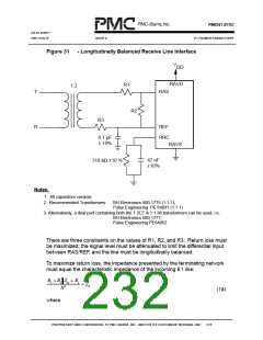
Figure 31
- Longitudinally Balanced Receive Line Interface
V
DD
RAVD
R1
1:2
T
RAS
R2
R3
R
REF
RRC
0.1 µF
± 10%
RAVS
47 nF
±10%
316 kΩ ±10 %
Notes:
1. All capacitors ceramic
2. Recommended Transformers:
BH Electronics 500-1775 (1:1:1);
Pulse Engineering PE 64931 (1:1:1)
3. Alternatively, a dual part containing both the 1:2CT & 1:1.36 transformers can be used, i.e.:
BH Electronics 500-1777;
Pulse Engineering PE64952
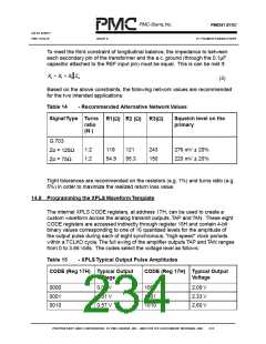
There are three constraints on the values of R1, R2, and R3: Return loss must
be maximized, the signal level must be attenuated to limit the differential input
between RAS/REF, and the line must be longitudinally balanced.
To maximize return loss, the impedance presented by the terminating network
must equal the characteristic impedance of the incoming E1 line:
R
R Z
N2
R
+
3
+
1
2
in
Z
=
0
(1a)
where
PROPRIETARY AND CONFIDENTIAL TO PMC-SIERRA, INC., AND FOR ITS CUSTOMERS’ INTERNAL USE
216

 PMC [ PMC-SIERRA, INC ]