PM6341 E1XC
DATA SHEET
PMC-910419
ISSUE 8
E1 FRAMER/TRANSCEIVER
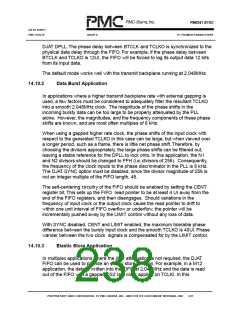
DJAT DPLL.The phase delay between BTCLK and TCLKO is synchronized to the
physical data delay through the FIFO. For example, if the phase delay between
BTCLK and TCLKO is 12UI, the FIFO will be forced to lag its output data 12 bits
from its input data.
The default mode works well with the transmit backplane running at 2.048MHz.
14.10.2
Data Burst Application
In applications where a higher transmit backplane rate with external gapping is
used, a few factors must be considered to adequately filter the resultant TCLKO
into a smooth 2.048MHz clock. The magnitude of the phase shifts in the
incoming bursty data can be too large to be properly attenuated by the PLL
alone. However, the magnitudes, and the frequency components of these phase
shifts are known, and are most often multiples of 8 kHz.
When using a gapped higher rate clock, the phase shifts of the input clock with
respect to the generated TCLKO in this case can be large, but when viewed over
a longer period, such as a frame, there is little net phase shift.Therefore, by
choosing the divisors appropriately, the large phase shifts can be filtered out,
leaving a stable reference for the DPLL to lock onto. In this application, the N1
and N2 divisors should be changed to FFH (i.e. divisors of 256). Consequently,
the frequency of the clock inputs to the phase discriminator in the PLL is 8 kHz.
The DJAT SYNC option must be disabled, since the divisor magnitude of 256 is
not an integer multiple of the FIFO length, 48.
The self-centering circuitry of the FIFO should be enabled by setting the CENT
register bit.This sets up the FIFO read pointer to be at least 4 UI away from the
end of the FIFO registers, and then disengages. Should variations in the
frequency of input clock or the output clock cause the read pointer to drift to
within one unit interval of FIFO overflow or underflow, the pointer will be
incrementally pushed away by the LIMIT control without any loss of data.
With SYNC disabled, CENT and LIMIT enabled, the maximum tolerable phase
difference between the bursty input clock and the smooth TCLKO is 40UI. Phase
wander between the two clock signals is compensated for by the LIMIT control.
14.10.3
Elastic Store Application
In multiplex applications where the jitter attenuation is not required, the DJAT
FIFO can be used to provide an elastic store function. For example, in a M12
application, the data is written into the FIFO at 2.048MHz and the data is read
out of the FIFO with a gapped DS2 rate clock applied on TCLKI. In this
PROPRIETARY AND CONFIDENTIAL TO PMC-SIERRA, INC., AND FOR ITS CUSTOMERS’ INTERNAL USE
222

 PMC [ PMC-SIERRA, INC ]