PM6341 E1XC
DATA SHEET
PMC-910419
ISSUE 8
E1 FRAMER/TRANSCEIVER
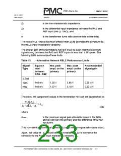
ZO
is the line characteristic impedance,
Zin
is the differential input impedance between the RAS and
REF input pins (≥ 10kΩ), and
N
is the transformer turns ratio (device-side to line-side).
The value of
should be much smaller than Zin to decrease the sensitivity to
R
2
the RSLC input impedance variability.
The overall gain of the terminating network must be such that the maximum
signal swing between the RAS and REF inputs is less than 1.96Vpeak. The
following table summarizes these limits:
Table 13
- Alternative Network RSLC Performance Limits
Signal
Type
Squelch
level
Min. peak
ampl. on the ampl. on the
Max. peak
Recommended
signal gain
between
RAS - REF
primary
primary
G.703
120Ω
75Ω
140 mV
140 mV
1.35 V
1.07 V
3.96 V
3.10 V
0.50 V/V
0.63 V/V
Therefore, the component values in the termination network are constrained to:
N R Z
( 2 )
in
≤
Amax
+
+
R3
R
R2 Z
1
in
(2a)
where
Amax
is the maximum signal gain allowable (given in the table
above) between the primary and the differential RAS/REF
input pins.
This constraint assumes that constraint (1a) is met (no signal reflections occur).
Again, the value of should be much smaller than Zin to decrease the
R
2
sensitivity to the RSLC input impedance variability.
PROPRIETARY AND CONFIDENTIAL TO PMC-SIERRA, INC., AND FOR ITS CUSTOMERS’ INTERNAL USE
217

 PMC [ PMC-SIERRA, INC ]