PM6341 E1XC
DATA SHEET
PMC-910419
ISSUE 8
E1 FRAMER/TRANSCEIVER
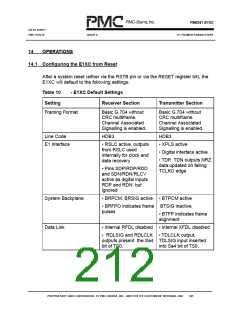
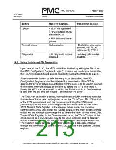
Setting
Receiver Section
Transmitter Section
Options
• ELST not bypassed
•
• RPCM outputs HDB3-
decoded PCM
• RFP indicates frame
pulses
Timing Options
Diagnostics
Not applicable
• Digital jitter attenuation
enabled, with TCLKO
referenced to BTCLK
• All diagnostic modes
disabled
• All diagnostic modes
disabled
14.2 Using the Internal FDLTransmitter
Upon reset of the E1XC, the XFDL should be disabled by setting the EN bit in
the XFDL Configuration Register to logic 0. If data is not ready to be transmitted,
the TDLINT[x] output should also be masked by setting the INTE bit to logic 0.
When a frame (or frames) of data are ready to be transmitted, the XFDL
Configuration Register should be initialized for transmission: if the FCS is
desired, the CRC bit should be set to logic 1; if the block is to be used in interrupt
driven mode, interrupts should be enabled by setting the INTE bit to logic 1.
Finally, the XFDL can be enabled by setting the EN bit to logic 1. If no message
is sent after the EN bit is set to logic 1, an underrun will occur.
The XFDL can be used in a polled, interrupt driven, or DMA-controlled mode for
the transfer of frame data. In the polled mode, the TDLINT and TDLUDR outputs
of the XFDL are not used, and the processor controlling the XFDL must
periodically read the XFDL Status Register to determine when to write to the
XFDL Transmit Data Register. In the interrupt driven mode, the processor
controlling the XFDL uses either the TDLINT output, or the main processor INTB
output and the interrupt source registers, to determine when to write to the XFDL
Transmit Data Register. In the DMA controlled mode, the TDLINT output of the
XFDL is used as a DMA request input to the DMA controller, and the TDLUDR
output is used as an interrupt to the processor to allow handling of exceptions.
The TDLUDR output can also be enabled to generate a processor interrupt
through the common INTB output via the TDLUDRE bit in the Datalink Options
register.
PROPRIETARY AND CONFIDENTIAL TO PMC-SIERRA, INC., AND FOR ITS CUSTOMERS’ INTERNAL USE
197

 PMC [ PMC-SIERRA, INC ]