S/UNI®-8x155 ASSP Telecom Standard Product Data Sheet
Released
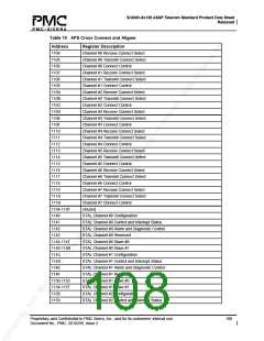
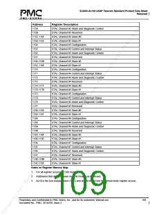
Address
115A
Register Description
STAL Channel #2 Alarm and Diagnostic Control
115B
STAL Channel #2 Reserved
115C-115F
1160-1163
1164
1165
1166
STAL Channel #2 Slave #0
STAL Channel #2 Slave #1
STAL Channel #3 Configuration
STAL Channel #3 Control and Interrupt Status
STAL Channel #3 Alarm and Diagnostic Control
STAL Channel #3 Reserved
1167
1168-116B
116C-116F
1170
1171
1172
STAL Channel #3 Slave #0
STAL Channel #3 Slave #1
STAL Channel #4 Configuration
STAL Channel #4 Control and Interrupt Status
STAL Channel #4 Alarm and Diagnostic Control
STAL Channel #4 Reserved
1173
1174-1177
1178-117B
117C
117D
117E
STAL Channel #4 Slave #0
STAL Channel #4 Slave #1
STAL Channel #5 Configuration
STAL Channel #5 Control and Interrupt Status
STAL Channel #5 Alarm and Diagnostic Control
STAL Channel #5 Reserved
117F
1180-1183
1184-1187
1188
1189
118A
STAL Channel #5 Slave #0
STAL Channel #5 Slave #1
STAL Channel #6 Configuration
STAL Channel #6 Control and Interrupt Status
STAL Channel #6 Alarm and Diagnostic Control
STAL Channel #6 Reserved
118B
118C-118F
1190-1193
1194
1195
1196
STAL Channel #6 Slave #0
STAL Channel #6 Slave #1
STAL Channel #7 Configuration
STAL Channel #7 Control and Interrupt Status
STAL Channel #7 Alarm and Diagnostic Control
STAL Channel #7 Reserved
1197
1198-119B
119C-119F
STAL Channel #7 Slave #0
STAL Channel #7 Slave #1
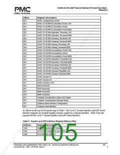
Notes on Register Memory Map:
1. For all register accesses, CSB must be low.
2. Addresses that are not shown must be treated as Reserved.
3. A[13] is the test resister select (TRS) and should be set low for normal mode register access.
Proprietary and Confidential to PMC-Sierra, Inc., and for its customers’ internal use.
Document No.: PMC- 2010299, Issue 2
109

 PMC [ PMC-SIERRA, INC ]