S/UNI®-8x155 ASSP Telecom Standard Product Data Sheet
Released
Address
1035
1036
1037
1038
1039
103A
103B
103C
103D
103E
103F
1048
1049
104A
104B
104C
104D
104E
104F
1058
1059
105A
105B
105C
105D
105E
105F
1068
1069
106A
106B
106C
106D
106E
106F
1070 -10FF
Register Description
RUL3 Reserved
RUL3 Reset
RUL3 APS DLL Control Status
TAOP APS Link #0 Control
TAOP APS Link #0 Diagnostic
TAOP APS Link #0 Reserved
TAOP APS Link #0 Reserved
TAOP APS Link #1 Control
TAOP APS Link #1 Diagnostic
TAOP APS Link #1 Reserved
TAOP APS Link #1 Reserved
RAOP APS Link #0 Control/Interrupt Enable
RAOP APS Link #0 Status/Interrupt Status
RAOP APS Link #0 Section BIP-8 LSB
RAOP APS Link #0 Section BIP-8 MSB
RAOP APS Link #1 Control/Interrupt Enable
RAOP APS Link #1 Status/Interrupt Status
RAOP APS Link #1 Section BIP-8 LSB
RAOP APS Link #1 Section BIP-8 MSB
RAPS APS Link #0 Configuration
RAPS APS Link #0 Status
RAPS APS Link #0 Reserved
RAPS APS Link #0 Reserved
RAPS APS Link #1 Configuration
RAPS APS Link #1 Status
RAPS APS Link #1 Reserved
RAPS APS Link #1 Reserved
BIMX Reserved
BIMX Reserved
BIMX Reserved
BIMX Reserved
BIMX Reserved
BIMX Reserved
BIMX Reserved
BIMX Reserved
Unused
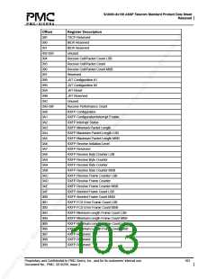
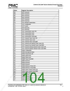
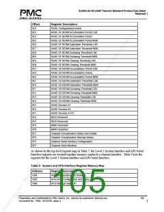
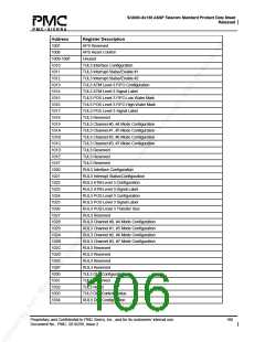
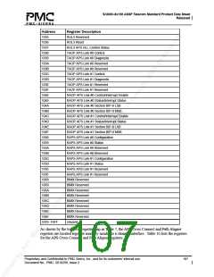
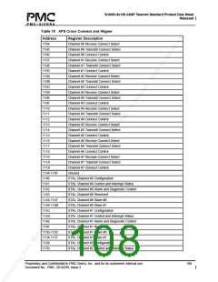
As shown by the top level register map in Table 7, the APS Cross Connect and Path Aligner
registers are located together memory similar to a channel interface. Table 10 lists the registers
for the APS Cross Connect and Path Aligner registers.
Proprietary and Confidential to PMC-Sierra, Inc., and for its customers’ internal use.
Document No.: PMC- 2010299, Issue 2
107

 PMC [ PMC-SIERRA, INC ]