PEX 8532 Transparent Mode Port Registers
PLX Technology, Inc.
11.7
Power Management Capability Registers
This section details the PEX 8532 Power Management Capability registers. The register map is defined
in Table 11-5.
Table 11-5. Power Management Capability Register Map (All Ports)
31 30 29 28 27 26 25 24 23 22 21 20 19 18 17 16
Power Management Capability
15 14 13 12 11 10 9 8 7 6 5 4 3 2 1 0
Next Capability Pointer (48h)
Capability ID (01h)
40h
44h
Power Management Control/
Data
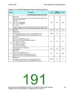
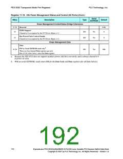
Power Management Status and Control
Status Bridge Extensions
Register 11-17. 40h Power Management Capability (All Ports)
Serial
EEPROM
Bit(s)
Description
Type
Default
Capability ID
7:0
RO
Yes
01h
Set to 01h, indicating that the data structure currently being pointed to is the
PCI Power Management data structure.
Next Capability Pointer
15:8
RO
RO
RO
Yes
Yes
No
48h
Default 48h points to the Message Signaled Interrupt Capability register.
Version
18:16
010b
Default 010b indicates compliance with the PCI Power Mgmt. r1.1.
PME Clock
19
20
21
0
0
0
Cleared to 0, as required by the PCI Express Base r1.0a.
Reserved
Device-Specific Initialization
RO
RO
Yes
Yes
Default 0 indicates that Device-Specific Initialization is not required.
AUX Current
Not supported
24:22
000b
Default 000b indicates that the PEX 8532 does not support Auxiliary Current
requirements.
D1 Support
25
26
RO
RO
RO
No
No
Yes
0
0
Not supported
Default 0 indicates that the PEX 8532 does not support the D1 power state.
D2 Support
Not supported
Default 0 indicates that the PEX 8532 does not support the D2 power state.
PME Support
31:27
11001b
Default 11001b indicates that the corresponding PEX 8532 port forwards
PME messages in the D0, D3hot, and D3cold power states.
168
ExpressLane PEX 8532AA/BA/BB/BC 8-Port/32-Lane Versatile PCI Express Switch Data Book
Copyright © 2007 by PLX Technology, Inc. All Rights Reserved – Version 1.6

 PLX [ PLX TECHNOLOGY ]