February, 2007
Message Signaled Interrupt Capability Registers
11.8
Message Signaled Interrupt Capability Registers
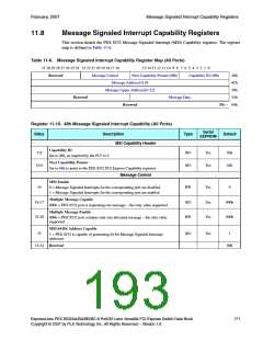
This section details the PEX 8532 Message Signaled Interrupt (MSI) Capability registers. The register
map is defined in Table 11-6.
Table 11-6. Message Signaled Interrupt Capability Register Map (All Ports)
31 30 29 28 27 26 25 24 23 22 21 20 19 18 17 16 15 14 13 12 11 10 9 8 7 6 5 4 3 2 1 0
Reserved Message Control
Message Address[31:0]
Next Capability Pointer (68h)
Capability ID (05h)
48h
4Ch
Message Upper Address[63:32]
50h
Reserved
Message Data
54h
Reserved
58h – 64h
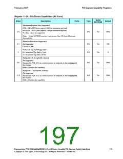
Register 11-19. 48h Message Signaled Interrupt Capability (All Ports)
Serial
EEPROM
Bit(s)
Description
MSI Capability Header
Type
Default
Capability ID
7:0
RO
RO
Yes
Yes
05h
68h
Set to 05h, as required by the PCI r2.3.
Next Capability Pointer
15:8
Set to 68h to point to the PEX 8532 PCI Express Capability registers.
Message Control
MSI Enable
16
RW
RO
Yes
Yes
Yes
0
0 = Message Signaled Interrupts for the corresponding port are disabled
1 = Message Signaled Interrupts for the corresponding port are enabled
Multiple Message Capable
19:17
22:20
000b
000b
000b = PEX 8532 port is requesting one message – the only value supported
Multiple Message Enable
RW
000b = PEX 8532 port contains only one allocated message – the only value
supported
MSI 64-Bit Address Capable
23
RO
Yes
1
1 = PEX 8532 is capable of generating 64-bit Message Signaled Interrupt
addresses
31:24 Reserved
00h
ExpressLane PEX 8532AA/BA/BB/BC 8-Port/32-Lane Versatile PCI Express Switch Data Book
Copyright © 2007 by PLX Technology, Inc. All Rights Reserved – Version 1.6
171

 PLX [ PLX TECHNOLOGY ]