Chapter 11 PEX 8532 Transparent Mode
Port Registers
11.1
Introduction
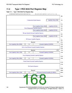
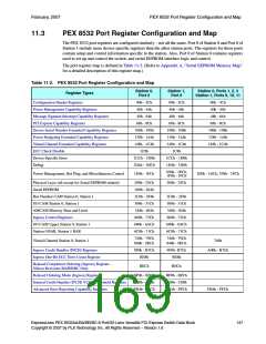
This chapter defines the PEX 8532 Transparent mode port registers. The PEX 8532 ports have their own
Configuration, Capability, Control, and Status register space. The register mapping is the same for each
port. (Refer to Table 11-1.) This chapter also presents the PEX 8532 programmable registers and the
order in which they appear in the register map. Register descriptions, when applicable, include details
regarding their use and meaning in the upstream and downstream ports. (Refer to Figure 11-1.)
NT Port registers are defined in Chapter 15, “NT Port Virtual Interface Registers,” and Chapter 16,
“NT Port Link Interface Registers.”
For further details regarding register names and descriptions, refer to the following specifications:
• PCI r2.3
• PCI Power Mgmt. r1.1
• PCI-to-PCI Bridge r1.1
• PCI Express Base r1.0a
Note: For the PEX 8532 to properly route Memory and I/O requests and Completions, each station
contains Content Addressable Memory (CAM) registers that hold mirror copies of certain
registers in each port. Refer to the PEX 85XX EEPROM – PEX 8532/8524/8516 Design Note,
Section 6.12, “Shadowed Registers.” If the registers that are shadowed are programmed by the
serial EEPROM to non-default values, the corresponding CAM registers must be programmed
by serial EEPROM to contain the same values as the shadowed registers.
ExpressLane PEX 8532AA/BA/BB/BC 8-Port/32-Lane Versatile PCI Express Switch Data Book
Copyright © 2007 by PLX Technology, Inc. All Rights Reserved – Version 1.6
145

 PLX [ PLX TECHNOLOGY ]