February, 2007
PEX 8532 PCI Express Power Management Support
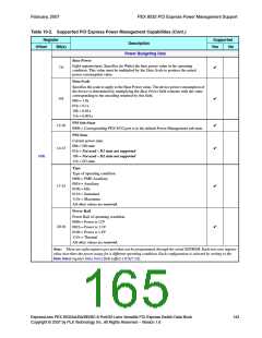
Table 10-2. Supported PCI Express Power Management Capabilities (Cont.)
Register
Supported
Description
Offset
Bit(s)
Yes
No
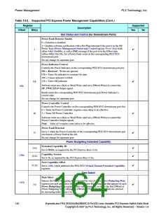
Power Budgeting Data
Base Power
Eight registers/port. Specifies (in Watts) the base power value in the operating
condition. This value must be multiplied by the Data Scale to produce the actual
power consumption value.
7:0
✔
Data Scale
Specifies the scale to apply to the Base Power value. The device power consumption of
the device is determined by multiplying the Base Power field contents with the value
corresponding to the encoding returned by this field.
00b = 1.0x
01b = 0.1x
10b = 0.01x
11b = 0.001x
✔
9:8
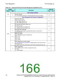
PM Sub-State
✔
✔
12:10
14:13
000b = Corresponding PEX 8532 port is in the default Power Management sub-state
PM State
Current power state.
00b = D0 state
01b = Not used – D1 state not supported
10b = Not used – D2 state not supported
11b = D3 state
140h
Type
Type of operating condition.
000b = PME Auxiliary
001b = Auxiliary
010b = Idle
✔
17:15
011b = Sustained
111b = Maximum
All other values are reserved.
Power Rail
Power Rail of operating condition.
000b = Power is 12V
001b = Power is 3.3V
010b = Power is 1.8V
111b = Thermal
✔
20:18
All other values are reserved.
Note: There are eight registers per port that can be programmed, through the serial EEPROM. Each non-zero register
value describes the power usage for a different operating condition. Each configuration is selected by writing to the
Data Select register Data Select field (offset 13Ch[7:0]).
ExpressLane PEX 8532AA/BA/BB/BC 8-Port/32-Lane Versatile PCI Express Switch Data Book
Copyright © 2007 by PLX Technology, Inc. All Rights Reserved – Version 1.6
143

 PLX [ PLX TECHNOLOGY ]