Power Management
PLX Technology, Inc.
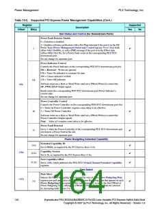
Table 10-2. Supported PCI Express Power Management Capabilities (Cont.)
Register
Supported
Description
Offset
Bit(s)
Yes
No
Power Management Status and Control
Power State
This field is used to determine the current power state of the port, and to set the port
into a new power state.
00b = D0
01b = D1 – Not supported
10b = D2 – Not supported
11b = D3hot
✔
1:0
If software attempts to write an unsupported state to this field, the Write operation
completes normally; however, the data is discarded and no state change occurs.
PME Enable
0 = Disables PME generation by the corresponding PEX 8532 porta
1 = Enables PME generation by the corresponding PEX 8532 port
✔
✔
8
Data Select
RW by Serial EEPROM mode onlyb.
Bits [12:9] select the Data and Data Scale registers.
0h = D0 power consumed
12:9
3h = D3hot power consumed
4h = D0 power dissipated
7h = D3hot power dissipated
44h
✔
RO for hardware auto-configuration.
Data Scale
RW by Serial EEPROM mode onlyb.
There are four internal Data Scale registers per port.
Bits [12:9], Data Select, select the Data Scale register.
✔
✔
14:13
15
PME Status
0 = PME is not generated by the corresponding PEX 8532 porta
1 = PME is being generated by the corresponding PEX 8532 port
Power Management Control/Status Bridge Extensions
B2/B3 Support
✔
✔
22
23
Cleared to 0, as required by the PCI Power Mgmt. r1.1.
Bus Power/Clock Control Enable
Cleared to 0, as required by the PCI Power Mgmt. r1.1.
Power Management Data
Data
RW by Serial EEPROM mode onlyb.
There are four internal Data registers per port.
Bits [12:9], Data Select, select the Data register.
31:24
✔
a. Because the PEX 8532 does not support auxiliary power, this bit is not sticky, and is always cleared to 0
at power-on reset.
b. With no serial EEPROM, reads return 00h for the Data Scale and Data registers (for all Data Selects).
138
ExpressLane PEX 8532AA/BA/BB/BC 8-Port/32-Lane Versatile PCI Express Switch Data Book
Copyright © 2007 by PLX Technology, Inc. All Rights Reserved – Version 1.6

 PLX [ PLX TECHNOLOGY ]