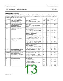
Philips Semiconductors
Preliminary specification
Fault-tolerant CAN transceiver
TJA1054
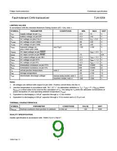
LIMITING VALUES
In accordance with the Absolute Maximum Rating System (IEC 134); note 1.
SYMBOL
PARAMETER
CONDITIONS
MIN.
−0.3
MAX.
UNIT
VCC
supply voltage on pin VCC
battery voltage on pin BAT
DC voltage on pins 2 to 6
DC voltage on pin CANH
DC voltage on pin CANL
+6
V
VBAT
Vn
−0.3
−0.3
−40
+40
V
V
V
V
V
VCC + 0.3
+40
VCANH
VCANL
Vtrt(n)
−40
+40
transient voltage on
see Fig.6
−150
+100
pins CANH and CANL
VWAKE
IWAKE
VINH
VRTH
VRTL
RRTH
RRTL
Tvj
DC input voltage on pin WAKE
DC input current on pin WAKE
DC output voltage on pin INH
DC voltage on pin RTH
−
VBAT + 0.3
−
V
−15
−0.3
−0.3
−0.3
500
500
−40
−55
−2.0
−200
mA
V
VBAT + 0.3
VBAT + 1.2
VBAT + 1.2
16000
16000
+150
V
DC voltage on pin RTL
V
termination resistance on pin RTH
termination resistance on pin RTL
virtual junction temperature
storage temperature
Ω
Ω
note 2
°C
°C
kV
V
Tstg
+150
Vesd
electrostatic discharge voltage
human body model; note 3
machine model; note 4
+2.0
+200
Notes
1. All voltages are defined with respect to pin GND. Positive current flows into the IC.
2. Junction temperature in accordance with “IEC 747-1”. An alternative definition is: Tvj = Tamb + P × Rth(vj-a) where
th(vj-a) is a fixed value to be used for the calculation of Tvj. The rating for Tvj limits the allowable combinations of
R
power dissipation (P) and operating ambient temperature (Tamb).
3. Equivalent to discharging a 100 pF capacitor through a 1.5 kΩ resistor.
4. Equivalent to discharging a 200 pF capacitor through a 10 Ω resistor and a 0.75 µH coil.
THERMAL CHARACTERISTICS
SYMBOL
PARAMETER
CONDITIONS
in free air
VALUE
UNIT
Rth(vj-a)
thermal resistance from junction to ambient
120
K/W
QUALITY SPECIFICATION
Quality specification in accordance with “SNW-FQ-611-Part-E”.
1999 Feb 11
9

 NXP [ NXP ]