Philips Semiconductors
Preliminary specification
Fault-tolerant CAN transceiver
TJA1054
The differential receiver threshold voltage is set at
FUNCTIONAL DESCRIPTION
−3.2 V typically (VCC = 5 V). This ensures correct
reception with a noise margin as high as possible in the
normal operating mode and in the event of failures 1, 2,
4 and 6a. These failures, or recovery from them, do not
destroy ongoing transmissions.
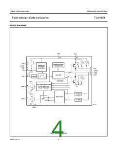
The TJA1054 is the interface between the CAN protocol
controller and the physical wires of the CAN bus
(see Fig.7). It is primarily intended for low speed
applications, up to 125 kBaud, in passenger cars.
The device provides differential transmit capability to the
CAN bus and differential receive capability to the CAN
controller.
Failures 3 and 6 are detected by comparators connected
to the CANH and CANL bus lines, respectively. If the
comparator threshold is exceeded for a certain period of
time, the reception is switched to the single-wire mode.
This time is needed to avoid false triggering by external RF
fields. Recovery from these failures is detected
automatically after a certain time-out (filtering) and no
transmission is lost. In the event of failure 3 the CANH
driver and pin RTH are switched off. In the event of
failure 6 the CANL driver and pin RTL are switched off.
The pull-up current on pin RTL and the pull-down current
on pin RTH will not be switched off.
To reduce RFI, the rise and fall slope are limited. This
allows the use of an unshielded twisted pair or a parallel
pair of wires for the bus lines. Moreover, it supports
transmission capability on either bus line if one of the wires
is corrupted. The failure detection logic automatically
selects a suitable transmission mode.
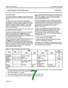
In normal operating mode (no wiring failures) the
differential receiver is output on pin RXD (see Fig.1).
The differential receiver inputs are connected to
pins CANH and CANL through integrated filters.
The filtered input signals are also used for the single-wire
receivers. The receivers connected to pins CANH
and CANL have threshold voltages that ensure a
maximum noise margin in single-wire mode.
Failures 3a, 4 and 7 initially result in a permanent
dominant level on pin RXD. After a time-out, the CANL
driver and pin RTL are switched off (failures 4 and 7) or
the CANH driver and pin RTH are switched off (failure 3a).
Only a weak pull-up on pin RTL or a weak pull-down on
pin RTH remains. Reception continues by switching to the
single-wire mode via pins CANH or CANL. When
failures 3a, 4 or 7 are removed, the recessive bus levels
are restored. If the differential voltage remains below the
recessive threshold level for a certain period of time,
reception and transmission switch back to the differential
mode.
A timer has been integrated at pin TXD. This timer
prevents the TJA1054 from driving the bus lines to a
permanent dominant state.
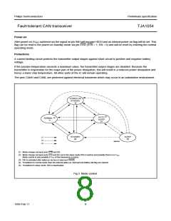
Failure detector
The failure detector is fully active in the normal operating
mode. After the detection of a single bus failure the
detector switches to the appropriate mode (see Table 1).
If any of the wiring failure occurs, the output signal on
pin ERR will become LOW. On error recovery, the output
signal on pin ERR will become HIGH again.
Table 1 Bus failures
During all single-wire transmissions, the EMC
performance (both immunity and emission) is worse than
in the differential mode. The integrated receiver filters
suppress any HF noise induced into the bus wires.
The cut-off frequency of these filters is a compromise
between propagation delay and HF suppression. In the
single-wire mode, LF noise cannot be distinguished from
the required signal.
FAILURE
DESCRIPTION
CANH wire interrupted
1
2
CANL wire interrupted
3
CANH short-circuited to battery
CANH short-circuited to VCC
CANL short-circuited to ground
CANH short-circuited to ground
CANL short-circuited to battery
CANL short-circuited to VCC
CANL mutually short-circuited to CANH
3a
4
5
6
6a
7
1999 Feb 11
6

 NXP [ NXP ]