Philips Semiconductors
Preliminary specification
Fault-tolerant CAN transceiver
TJA1054
If VCC is provided the wake-up request can be read on the
ERR or RXD outputs, so the external microcontroller can
wake-up the transceiver (switch to normal operating
mode) via pins STB and EN.
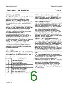
Low power modes
The transceiver provides 3 low power modes which can be
entered and exited via pins STB and EN (see Table 2 and
Fig.3).
To prevent false wake-up due to transients or RF fields,
the wake-up voltage levels have to be maintained for a
certain period of time. In the low power modes the failure
detection circuit remains partly active to prevent an
increased power consumption in the event of
failures 3, 3a, 4 and 7.
The Sleep mode is the mode with the lowest power
consumption. Pin INH is switched to high-impedance for
deactivation of the external voltage regulator. Pin CANL is
biased to the battery voltage via pin RTL. If the supply
voltage is provided pins RXD and ERR will signal the
wake-up interrupt signal.
Pin INH is set to floating only during the goto-sleep
command and stays floating during the Sleep mode. If
pin INH is set to floating, pin INH will not be set to
HIGH-level again just by a mode change to normal
operating mode. Pin INH will be set to HIGH-level by the
following events only:
The standby mode will react the same as the Sleep mode
but with a HIGH-level on pin INH.
The power-on standby mode is the same as the standby
mode with the battery power-on flag instead of the
wake-up interrupt signal on pin ERR. The output on
pin RXD will show the wake-up interrupt. This mode is only
for reading out the power-on flag.
• power-on (VBAT switching-on at cold start)
• rising or falling edge on pin WAKE
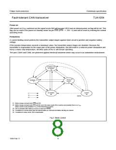
Wake-up requests are recognized by the transceiver when
a dominant signal is detected on either bus line or if
pin WAKE detects an edge (rising or falling) which stays
longer HIGH or LOW respectively during a certain period
of time. On a wake-up request the transceiver will set the
output on pin INH which can be used to activate the
external supply voltage regulator.
• a message with 5 consecutive dominant bits during
pin EN or pin STB is at LOW-level.
The signals on pins STB and EN will internally be set to
LOW-level when VCC is below a certain threshold voltage
so providing fail safe functionality.
Table 2 Normal operating and low power modes
ERR
RXD
RTL
SWITCHED
TO
MODE
STB
EN
LOW
HIGH
LOW
HIGH
Goto-sleep
command
0
1
VBAT
wake-up interrupt
signal;
notes 2 and 3
wake-up interrupt
signal;
notes 2 and 3
Sleep
0
0
1
0(1)
0
VBAT
VBAT
Standby
Power-on
standby
0
VBAT power-on flag;
notes 2 and 4
wake-up interrupt
signal;
VBAT
notes 2 and 3
Normal
operating
1
1
error flag
no error
flag
dominant
received data
recessive
received data
VCC
Notes
1. In case the goto-sleep command was used before. When VCC drops pin EN will become LOW, but this does not effect
the internal functions due to the fail safe functionality.
2. If the supply voltage VCC is present.
3. Wake-up interrupts are released when entering the normal operating mode.
4. VBAT power-on flag will be reset when entering the normal operating mode.
1999 Feb 11
7

 NXP [ NXP ]