Philips Semiconductors
Preliminary specification
Fault-tolerant CAN transceiver
TJA1054
Power-on
After power-on (VBAT switched on) the signal on pin INH will become HIGH and an internal power-on flag will be set. This
flag can be read in the power-on standby mode via pin ERR (STB = 1; EN = 0) and will be reset by entering the normal
operating mode.
Protections
A current limiting circuit protects the transmitter output stages against short-circuit to positive and negative battery
voltage.
If the junction temperature exceeds a maximum value, the transmitter output stages are disabled. Because the
transmitter is responsible for the major part of the power dissipation, this will result in a reduced power dissipation and
hence a lower chip temperature. All other parts of the IC will remain operating.
The pins CANH and CANL are protected against electrical transients which may occur in an automotive environment.
handbook, full pagewidth
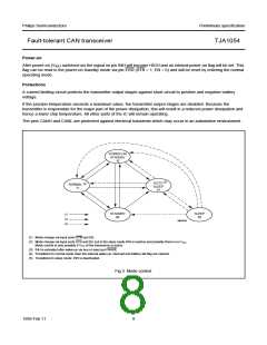
POWER-ON
STANDBY
10
(5)
GOTO
SLEEP
01
(4)
NORMAL
11
STANDBY
00
SLEEP
00
(1)
(2)
(3)
MBK949
(1) Mode change via input ports STB and EN.
(2) Mode change via input ports STB and EN, but in the sleep mode INH is inactive and possibly there is no VCC
Mode control is only possible if VCC of the transceiver is active.
.
(3) INH is activated after wake-up via bus or input port WAKE.
(4) Transitions to normal mode clear the internal wake-up: interrupt and battery fail flag are cleared.
(5) Transitions to sleep mode: INH is deactivated.
Fig.3 Mode control.
1999 Feb 11
8

 NXP [ NXP ]