Philips Semiconductors
Objective specification
Integrated PAL and PAL/NTSC TV
processors
TDA8360; TDA8361; TDA8362
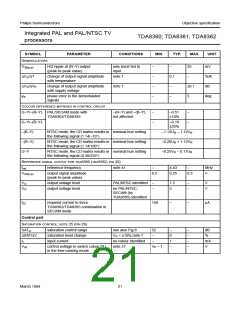
SYMBOL
PARAMETER
CONDITIONS
MIN.
TYP.
MAX.
UNIT
DEMODULATORS
V30(p-p)
H/2 ripple at (R−Y) output
(peak-to-peak value)
only burst fed to
input
−
−
−
−
−
25
mV
∆VO/∆T
∆VO/∆VP
ϕe
change of output signal amplitude
with temperature
note 7
0.1
−
−
%/K
dB
change of output signal amplitude
with supply voltage
note 7
±0.1
5
phase error in the demodulated
signals
−
deg
COLOUR DIFFERENCE MATRIXES IN CONTROL CIRCUIT
G−Y/−(R−Y) PAL/SECAM mode with
−(R−Y) and −(B−Y)
not affected
−
−
−0.51
±10%
−
−
TDA8362/TDA8395
G−Y/−(B−Y)
−0.19
±25%
−(B−Y)
−(R−Y)
G−Y
NTSC mode; the CD matrix results in nominal hue setting
the following signal (1.14/−10°)
−1.12UR − 1.12VR
−0.20UR + 1.12VR
−0.25VR − 0.17UR
NTSC mode; the CD matrix results in nominal hue setting
the following signal (1.14/100°)
NTSC mode; the CD matrix results in nominal hue setting
the following signal (0.30/235°)
REFERENCE SIGNAL OUTPUT FOR TDA8395 (TDA8362; PIN 32)
fref
reference frequency
note 41
−
4.43
0.25
−
MHz
V
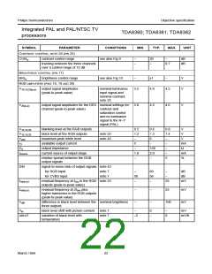
V32(p-p)
output signal amplitude
(peak-to-peak value)
0.2
0.3
VO
VO
output voltage level
output voltage level
PAL/NTSC identified
−
−
1.5
5
−
−
V
V
no PAL/NTSC;
SECAM (by
TDA8395) identified
I32
required current to force
TDA8362/TDA8395 combination in
SECAM mode
150
−
−
µA
Control part
SATURATION CONTROL; NOTE 25 (PIN 26)
SATcr
∆SAT/∆V
II
saturation control range
saturation level change
input current
see also Fig.8
VP = ±10%;note 7
no colour identified
note 37
52
−
0
1
−
−
−
−
−
dB
%
−
−
mA
V
Vctr
control voltage to switch colour PLL
in the free-running mode
VP − 1
March 1994
21

 NXP [ NXP ]