Philips Semiconductors
Product specification
Multimedia bridge, high performance
Scaler and PCI circuit (SPCI)
SAA7146A
9
ELECTRICAL OPERATING CONDITIONS
• Operating time: the circuit is designed to be able to operate continuously
• Backup: no backup capability (standby) will be provided internally
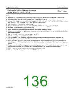
• Handling: inputs and outputs are protected against electrostatic discharge in normal handling. However, to be totally
safe, it is desirable to take normal handling precautions appropriate to handling MOS devices.
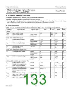
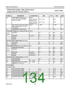
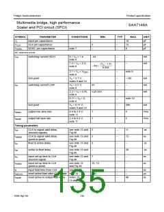
10 CHARACTERISTICS
VDDD = 3.3 V for the internal core and for the I/O pad section. Tamb = 0 to 70 °C; unless otherwise specified.
SYMBOL
PARAMETER
CONDITIONS
MIN.
TYP.
MAX.
UNIT
Supply
VDDD
IDDD
digital supply voltage
digital supply current
3.0
3.3
3.6
V
video overlay
RGB mode
−
400
−
mA
Data, clock and control inputs
VIL
LOW-level input voltage
clocks
−0.5
−0.5
2.4
2.0
−
−
−
−
−
−
−
+0.6
+0.8
5.5
5.5
1
V
other outputs
clocks
V
VIH
HIGH-level input voltage
V
other inputs
VIL = 0 V
V
ILI
Ci
input leakage current
input capacitance
µA
pF
−
10
Data, clock and control outputs; note 1
VOL
LOW-level output voltage
clocks
0
0
−
−
0.6
0.6
V
V
other outputs;
note 2
VOH
HIGH-level output voltage
clocks
2.6
2.4
−
−
VDDD
VDDD
V
V
other outputs;
note 2
I2C-bus, SDA and SCL (pins 176 and 175)
VIL
LOW-level input voltage
(VDDI2C related input levels)
note 3
note 3
note 3
−0.5
−
−
−
+0.3VDDI2C
VDDI2C + 0,5
−
V
V
V
VIH
Vhys
HIGH-level input voltage
(VDDI2C related input levels)
0.7VDDI2C
hysteresis of Schmitt trigger
inputs (VDDI2C related input
levels)
0.05VDDI2C
VOL1
VOL2
LOW-level output voltage
(open-drain or open-collector)
at 3 mA sink
current
0
0
−
−
0.4
0.6
LOW-level output voltage
(open-drain or open-collector)
at 6 mA sink
current
1998 Apr 09
133

 NXP [ NXP ]