Philips Semiconductors
Product specification
Multimedia bridge, high performance
Scaler and PCI circuit (SPCI)
SAA7146A
Table 116 BST instructions supported by the SAA7146A
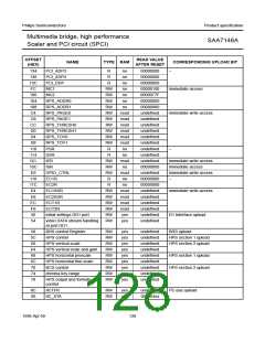
INSTRUCTION
DESCRIPTION
BYPASS
this mandatory instruction provides a minimum length serial path (1-bit) between TDI and TDO
when no test operation of the component is required
EXTEST
SAMPLE
this mandatory instruction allows testing of off-chip circuitry and board level interconnections
This mandatory instruction can be used to take a sample of the inputs during normal operation of
the component. It can also be used to preload data values into the latched outputs of the boundary
scan register
CLAMP
This optional instruction is useful for testing when not all ICs have BST. This instruction addresses
the bypass register while the boundary scan register is in external test mode
IDCODE
this optional instruction will provide information on the components manufacturer, part number and
version number
is the possibility to check for the correct ICs mounted after
production and determination of the version number of ICs
during field service.
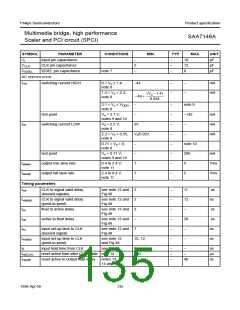
8.1
Initialization of boundary scan circuit
The Test Access Port (TAP) controller of an IC should be
in the reset state (TEST_LOGIC_RESET) when the IC is
in functional mode. This reset state also forces the
instruction register into a functional instruction such as
IDCODE or BYPASS.
When the IDCODE instruction is loaded into the BST
instruction register, the identification register will be
connected between TDI and TDO of the IC. The
identification register will load a component specific code
during the CAPTURE_DATA_REGISTER state of the TAP
controller and this code can subsequently be shifted out.
At board level this code can be used to verify component
manufacturer, type and version number. The device
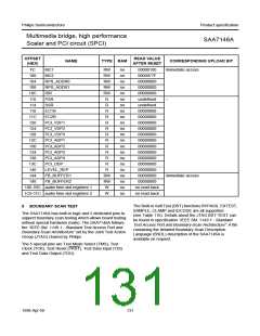
identification register contains 32 bits, numbered from
31 to 0, where bit 31 is the most significant bit (nearest to
TDI) and bit 0 is the least significant bit (nearest to TDO);
see Fig.46.
To solve the power-up reset, the standard specifies that
the TAP controller will be forced asynchronously to the
TEST_LOGIC_RESET state by setting the TRST pin
LOW.
8.2
Device identification codes
A device identification register is specified in “IEEE Std.
1149.1 - Standard Test Access Port and Boundary-Scan
Architecture”. It is a 32-bit register which contains fields for
the specification of the IC manufacturer, the IC part
number and the IC version number. Its biggest advantage
handbook, full pagewidth
MSB
LSB
31
28 27
0000
12 11
1
0
TDO
TDI
0111000101000110
16 bit part number
00000010101
1
4 bits
version
code
11 bit manufacturer
indentification
MBH751
Fig.46 32 bits of identification code.
132
1998 Apr 09

 NXP [ NXP ]