Philips Semiconductors
Product specification
Multimedia bridge, high performance
Scaler and PCI circuit (SPCI)
SAA7146A
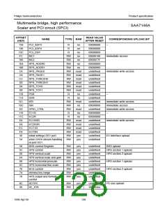
OFFSET
(HEX)
READ VALUE
AFTER RESET
NAME
TYPE RAM
CORRESPONDING UPLOAD BIT
FC
100
104
108
10C
110
114
118
11C
120
124
128
12C
130
134
138
13C
140
144
148
MC1
MC2
RW
RW
RW
RW
RW
R
no
no
no
no
no
no
no
no
no
no
no
no
no
no
no
no
no
no
no
no
no
no
00000100
0000077F
00000000
00000000
00000000
undefined
undefined
00000000
00000000
00000000
00000000
00000000
00000000
00000000
00000000
00000000
00000000
00000000
00000000
00000000
no read back
no read back
immediate access
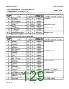
RPS_ADDR0
RPS_ADDR1
ISR
PSR
−
SSR
R
EC1R
R
EC2R
R
PCI_VDP1
PCI_VDP2
PCI_VDP3
PCI_ADP1
PCI_ADP2
PCI_ADP3
PCI_ADP4
PCI_DDP
LEVEL_REP
FB_BUFFER1
FB_BUFFER2
R
R
R
R
R
R
R
R
R
RW
RW
W
W
immediate access
180-1BC audio time slot registers 1
1C0-1FC audio time slot registers 2
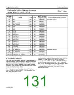
The Built-in Self Test (BST) functions BYPASS, EXTEST,
SAMPLE, CLAMP and IDCODE are all supported
(see Table 116). Details about the JTAG BST-TEST can
be found in specification “IEEE Std. 1149.1 - Standard
Test Access Port and Boundary-Scan Architecture”. A file
containing the detailed Boundary Scan Description
Language (BSDL) description of the SAA7146A is
available on request.
8
BOUNDARY SCAN TEST
The SAA7146A has built-in logic and 5 dedicated pins to
support boundary scan testing which allows board testing
without special hardware (nails). The SAA7146A follows
the “IEEE Std. 1149.1 - Standard Test Access Port and
Boundary-Scan Architecture” set by the Joint Test Action
Group (JTAG) chaired by Philips.
The 5 special pins are Test Mode Select (TMS), Test
Clock (TCK), Test Reset (TRST), Test Data Input (TDI)
and Test Data Output (TDO).
1998 Apr 09
131

 NXP [ NXP ]