Philips Semiconductors
Product specification
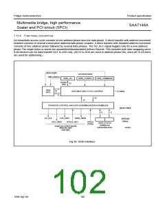
Multimedia bridge, high performance
Scaler and PCI circuit (SPCI)
SAA7146A
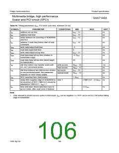
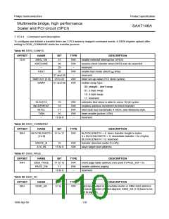
Table 93 Timing parameters (tPCI: PCI clock cycle time, minimum 30 ns)
SYMBOL
PARAMETER
address set-up time
CONDITIONS
MIN.
MAX.
UNIT
ns
tas
tah
talh
t
t
t
PCI − 15
PCI − 10
PCI − 15
−
−
−
address hold time
ns
ns
delay between de-asserting of RDN/WRN
and ALE
taz
address 3-state time before start of read
command
tPCI − 10
−
ns
tdhw
tdhr
tdsw
tdsrh
write data output hold time
read data input hold time
write data output set-up time
−3
−
−
−
−
ns
ns
ns
ns
0
tPCI − 15
read data input set-up time (relative to
handshake edge)
−0.7tPCI
tdsrd
tidl
read data input set-up time (dumb target,
no handshake)
20
−
ns
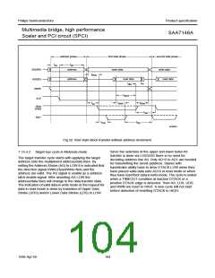
idle time before new transfer starts with
AS_ALE (increment mode)
write access
read access
2tPCI − 10
3tPCI − 10
−
−
−
−
ns
ns
ns
ns
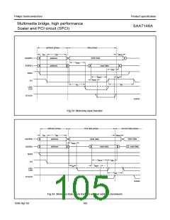
trwi
idle time between two data access strobes fast mode
in non-increment mode; this parameter
depends on FAST mode enable
RDY assertion time (Intel mode)
tPCI − 10
normal mode
2tPCI − 10
trdy
1.5tPCI
−
ns
tmin
delay from negative edge of RDN/WRN to note 1
de-assertion of RDY; TIMEOUT should be
adjusted to TIMEOUT = tmin + 1
−
(TIMEOUT − 0.5)tPCI ns
tdz
time until slave driven data lines have to
go to 3-state, after read cycle is finished
−
2.0 tPCI
ns
Note
1. Only relevant to stretch access cycles in Intel mode. tmin can be negative, i.e. RDY can be set to LOW before falling
edge of RDN/WRN.
1998 Apr 09
106

 NXP [ NXP ]