Philips Semiconductors
Product specification
Multimedia bridge, high performance
Scaler and PCI circuit (SPCI)
SAA7146A
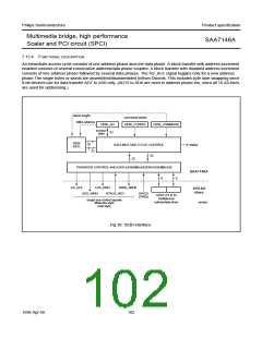
Since the SAA7146A will not evaluate the RDY signal until
TIMEOUT + 1 PCI cycles have elapsed, it is
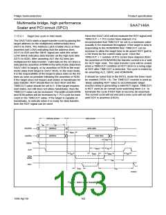
7.15.4.1 Target bus cycle in Intel mode
The SAA7146A starts a target transfer cycle by placing the
target address on the multiplexed address/data lines
(AD15 to AD0). The Address Latch Enable (ALE) is then
asserted (set LOW) indicating that the address lines
AD15 to AD0 and the SBHE signal are valid (the active
LOW SBHE indicates data transfer on the high byte lane
AD15 to AD8). After asserting ALE the AD lines are
multiplexed for data transfer. Valid data on the AD lines is
indicated by assertion of WRN in the write mode (data from
SAA7146A to target), or by assertion of RDN in the read
mode (data from target to SAA7146A). In the read mode,
it is the responsibility of the target to place data on the AD
lines as soon as possible following the assertion of RDN.
If the target does not require wait states or handshake for
data transfer, RDY should then be tied HIGH and the
TIMEOUT value should be set to 0. If the target requires
wait states, but still does not utilize handshake, then the
TIMEOUT value can be increased. The width of both WRN
and RDN pulses will be increased by 1 PCI cycle for each
count in the TIMEOUT value. If the target is capable of
handshake, to indicate when it is ready for data transfer,
then the RDY signal can be used.
recommended that TIMEOUT be set to a minimum value
(usually 0) for maximum throughput. If the target is slow in
responding to the RDN/WRN then TIMEOUT can be
increase to allow the target time to de-assert RDY (pull to
LOW level) for the current data cycle. Once the
TIMEOUT + 1 number of PCI cycles have elapsed (from
the assertion of RDN/WRN) the transfer control is in a ‘wait
for RDY high’ state. The data transfer cycle will be ended
when a TIMEOUT condition at RDY HIGH or a rising edge
of RDY after TIMEOUT is detected. The cycle is ended by
de-asserting ALE, SBHE and RDN/WRN.
It should be noted that in the INTEL mode the timer must
be enabled (TIEN = 0). The TIMEOUT counter is used as
‘delay sampling RDY’ value to accommodate target
reaction delay in generating a valid RDY signal. TIMEOUT
is NOT used as an overall cycle watchdog timer (i.e.: to
terminate the cycle if RDY fails to become de-asserted).
The current cycle will not end and a new cycle will not start
until RDY is asserted (HIGH).
address phase
data phase
handbook, full pagewidth
t
t
as
ah
address
write data
read data
AD(WR)
AD(RD)
t
dsw
address
t
dhr
SBHE
ALE
t
t
dsrd
dz
t
t
t
idl
t
dsrh
dhw
az
RDN
WRN
t
alh
RDY
t
t
rdy
min
MHB063
Fig.31 Intel style transfer.
1998 Apr 09
103

 NXP [ NXP ]