PCA9557
NXP Semiconductors
8-bit I2C-bus and SMBus I/O port with reset
7.4 Power-on reset
When power is applied to VDD, an internal Power-On Reset (POR) holds the PCA9557 in
a reset condition until VDD has reached VPOR. At that point, the reset condition is released
and the PCA9557 registers and I2C-bus/SMBus state machine will initialize to their default
states. Thereafter, VDD must be lowered below 0.2 V to reset the device.
7.5 RESET input
A reset can be accomplished by holding the RESET pin LOW for a minimum of tw(rst). The
PCA9557 registers and SMBus/I2C-bus state machine will be held in their default state
until the RESET input is once again HIGH. This input requires a pull-up resistor to VDD if
no active connection is used.
8. Characteristics of the I2C-bus
The I2C-bus is for 2-way, 2-line communication between different ICs or modules. The two
lines are a serial data line (SDA) and a serial clock line (SCL). Both lines must be
connected to a positive supply via a pull-up resistor when connected to the output stages
of a device. Data transfer may be initiated only when the bus is not busy.
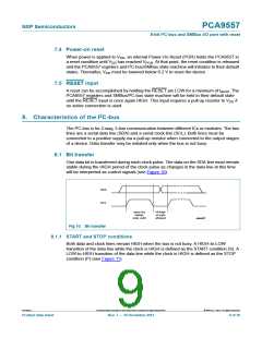
8.1 Bit transfer
One data bit is transferred during each clock pulse. The data on the SDA line must remain
stable during the HIGH period of the clock pulse as changes in the data line at this time
will be interpreted as control signals (see Figure 10).
SDA
SCL
data line
stable;
data valid
change
of data
allowed
mba607
Fig 10. Bit transfer
8.1.1 START and STOP conditions
Both data and clock lines remain HIGH when the bus is not busy. A HIGH-to-LOW
transition of the data line while the clock is HIGH is defined as the START condition (S). A
LOW-to-HIGH transition of the data line while the clock is HIGH is defined as the STOP
condition (P) (see Figure 11).
PCA9557
All information provided in this document is subject to legal disclaimers.
© NXP B.V. 2013. All rights reserved.
Product data sheet
Rev. 7 — 10 December 2013
9 of 30

 NXP [ NXP ]