Philips Semiconductors
Preliminary data
Low power, low price, low pin count (20 pin)
microcontroller with 4 kbyte OTP
87LPC764
Mode 0
measurements). TRn is a control bit in the Special Function Register
TCON (Figure 23). The GATE bit is in the TMOD register.
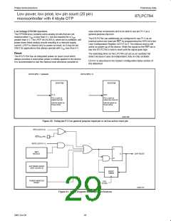
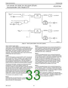
Putting either Timer into Mode 0 makes it look like an 8048 Timer,
which is an 8-bit Counter with a divide-by-32 prescaler. Figure 24
shows Mode 0 operation.
The 13-bit register consists of all 8 bits of THn and the lower 5 bits
of TLn. The upper 3 bits of TLn are indeterminate and should be
ignored. Setting the run flag (TRn) does not clear the registers.
In this mode, the Timer register is configured as a 13-bit register. As
the count rolls over from all 1s to all 0s, it sets the Timer interrupt
flag TFn. The count input is enabled to the Timer when TRn = 1 and
either GATE = 0 or INTn = 1. (Setting GATE = 1 allows the Timer to
be controlled by external input INTn, to facilitate pulse width
Mode 0 operation is the same for Timer 0 and Timer 1. See
Figure 24. There are two different GATE bits, one for Timer 1
(TMOD.7) and one for Timer 0 (TMOD.3).
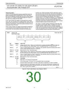
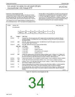
TCON
Address: 88h
Reset Value: 00h
Bit Addressable
7
6
5
4
3
2
1
0
TF1
TR1
TF0
TR0
IE1
IT1
IE0
IT0
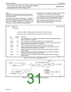
BIT
SYMBOL
FUNCTION
TCON.7
TF1
Timer 1 overflow flag. Set by hardware on Timer/Counter overflow. Cleared by hardware when the
interrupt is processed, or by software.
TCON.6
TCON.5
TR1
TF0
Timer 1 Run control bit. Set/cleared by software to turn Timer/Counter 1 on/off.
Timer 0 overflow flag. Set by hardware on Timer/Counter overflow. Cleared by hardware when the
processor vectors to the interrupt routine, or by software.
TCON.4
TCON.3
TR0
IE1
Timer 0 Run control bit. Set/cleared by software to turn Timer/Counter 0 on/off.
Interrupt 1 Edge flag. Set by hardware when external interrupt 1 edge is detected. Cleared by
hardware when the interrupt is processed, or by software.
TCON.2
TCON.1
TCON.0
IT1
IE0
IT0
Interrupt 1 Type control bit. Set/cleared by software to specify falling edge/low level triggered
external interrupts.
Interrupt 0 Edge flag. Set by hardware when external interrupt 0 edge is detected. Cleared by
hardware when the interrupt is processed, or by software.
Interrupt 0 Type control bit. Set/cleared by software to specify falling edge/low level triggered
external interrupts.
SU01172
Figure 23. Timer/Counter Control Register (TCON)
OVERFLOW
OSC/6
OSC/12
OR
C/T = 0
TLn
(5 BITS)
THn
(8 BITS)
TFn
INTERRUPT
Tn PIN
TRn
CONTROL
C/T = 1
TOGGLE
GATE
Tn PIN
INTn PIN
TnOE
SU01173
Figure 24. Timer/Counter 0 or 1 in Mode 0 (13-Bit Counter)
28
2001 Oct 26

 NXP [ NXP ]