Philips Semiconductors
Preliminary data
Low power, low price, low pin count (20 pin)
microcontroller with 4 kbyte OTP
87LPC764
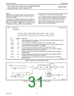
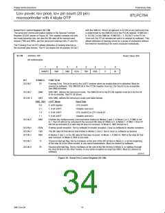
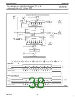
Serial Port Control Register (SCON)
with the SM0 bit. Which bit appears in SCON at any particular time
is determined by the SMOD0 bit in the PCON register. If SMOD0 =
0, SCON.7 is the SM0 bit. If SMOD0 = 1, SCON.7 is the FE bit.
Once set, the FE bit remains set until it is cleared by software. This
allows detection of framing errors for a group of characters without
the need for monitoring it for every character individually.
The serial port control and status register is the Special Function
Register SCON, shown in Figure 28. This register contains not only
the mode selection bits, but also the 9th data bit for transmit and
receive (TB8 and RB8), and the serial port interrupt bits (TI and RI).
The Framing Error bit (FE) allows detection of missing stop bits in
the received data stream. The FE bit shares the bit position SCON.7
SCON
Address: 98h
Reset Value: 00h
Bit Addressable
7
6
5
4
3
2
1
0
SM0/FE
SM1
SM2
REN
TB8
RB8
TI
RI
BIT
SYMBOL
FUNCTION
SCON.7
FE
Framing Error. This bit is set by the UART receiver when an invalid stop bit is detected. Must be
cleared by software. The SMOD0 bit in the PCON register must be 1 for this bit to be accessible.
See SM0 bit below.
SCON.7
SCON. 6
SM0
SM1
With SM1, defines the serial port mode. The SMOD0 bit in the PCON register must be 0 for this bit
to be accessible. See FE bit above.
With SM0, defines the serial port mode (see table below).
SM0, SM1 UART Mode
Baud Rate
0 0
0 1
0: shift register
1: 8-bit UART
2: 9-bit UART
3: 9-bit UART
CPU clock/6
Variable (see text)
CPU clock/32 or CPU clock/16
Variable (see text)
1 0
1 1
SCON.5
SM2
Enables the multiprocessor communication feature in Modes 2 and 3. In Mode 2 or 3, if SM2 is set
to 1, then Rl will not be activated if the received 9th data bit (RB8) is 0. In Mode 1, if SM2=1 then RI
will not be activated if a valid stop bit was not received. In Mode 0, SM2 should be 0.
SCON.4
SCON.3
SCON.2
REN
TB8
RB8
Enables serial reception. Set by software to enable reception. Clear by software to disable reception.
The 9th data bit that will be transmitted in Modes 2 and 3. Set or clear by software as desired.
In Modes 2 and 3, is the 9th data bit that was received. In Mode 1, it SM2=0, RB8 is the stop bit that
was received. In Mode 0, RB8 is not used.
SCON.1
SCON.0
TI
Transmit interrupt flag. Set by hardware at the end of the 8th bit time in Mode 0, or at the beginning
of the stop bit in the other modes, in any serial transmission. Must be cleared by software.
RI
Receive interrupt flag. Set by hardware at the end of the 8th bit time in Mode 0, or halfway through
the stop bit time in the other modes, in any serial reception (except see SM2). Must be cleared by
software.
SU01157
Figure 28. Serial Port Control Register (SCON)
31
2001 Oct 26

 NXP [ NXP ]