Philips Semiconductors
Preliminary data
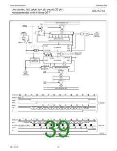
Low power, low price, low pin count (20 pin)
microcontroller with 4 kbyte OTP
87LPC764
Baud Rates
application. The Timer itself can be configured for either “timer” or
“counter” operation, and in any of its 3 running modes. In the most
typical applications, it is configured for “timer” operation, in the
auto-reload mode (high nibble of TMOD = 0010b). In that case the
baud rate is given by the formula:
The baud rate in Mode 0 is fixed: Mode 0 Baud Rate = CPU clock/6.
The baud rate in Mode 2 depends on the value of bit SMOD1 in
Special Function Register PCON. If SMOD1 = 0 (which is the value
on reset), the baud rate is 1/32 of the CPU clock frequency. If
SMOD1 = 1, the baud rate is 1/16 of the CPU clock frequency.
CPU clock frequencyń
192 (or 96 if SMOD1 + 1)
1 ) SMOD1
Mode 2 Baud Rate +
CPU clock frequency
32
Mode 1, 3 Baud Rate +
256 * (TH1)
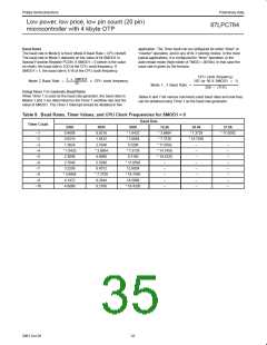
Using Timer 1 to Generate Baud Rates
When Timer 1 is used as the baud rate generator, the baud rates in
Modes 1 and 3 are determined by the Timer 1 overflow rate and the
value of SMOD1. The Timer 1 interrupt should be disabled in this
Tables 6 and 7 list various commonly used baud rates and how they
can be obtained using Timer 1 as the baud rate generator.
Table 9. Baud Rates, Timer Values, and CPU Clock Frequencies for SMOD1 = 0
Baud Rate
Timer Count
2400
0.4608
0.9216
1.3824
* 1.8432
2.3040
2.7648
3.2256
* 3.6864
4.1472
4.6080
4800
0.9216
1.8432
2.7648
* 3.6864
4.6080
5.5296
6.4512
* 7.3728
8.2944
9.2160
9600
19.2k
38.4k
57.6k
–1
–2
–3
–4
–5
–6
–7
–8
–9
–10
* 1.8432
* 3.6864
5.5296
* 3.6864
* 7.3728
* 11.0592
* 7.3728
* 14.7456
* 11.0592
–
–
–
–
–
–
–
–
–
–
–
–
–
–
–
–
* 7.3728
9.2160
* 14.7456
* 18.4320
* 11.0592
12.9024
* 14.7456
16.5888
* 18.4320
–
–
–
–
–
32
2001 Oct 26

 NXP [ NXP ]